Clamp
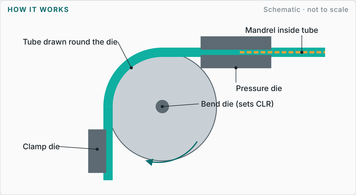
Clamp the tube to the bend die.
Manufacturing services · Chapter D · Method 26
Tube is clamped to a bend die and drawn around it, often over a mandrel, to make smooth bends without kinking or wrinkling.
How it works
A labelled schematic of the process (not to scale), and the four steps every job goes through.
Clamp the tube to the bend die.
Pressure die and mandrel support the tube.
The die rotates, drawing tube around the radius.
Rotate the tube and position for the next bend.
Reference figures
Typical industry values to help you plan. We agree the figures for your part on the drawing.
| Materials | Mild steel, stainless, aluminium and copper tube. |
|---|---|
| Finishes | Die marks under 0.8 mm accepted; free of wrinkles and creases. |
| Design guidance |
|
| Best suited to | Frames, handles, handrails, exhausts and fluid lines. |
| Watch-outs | Tolerances add up across bends; tight radii thin the outer wall. |
More in chapter D
Next step
Send a sketch, photo, sample or CAD file with your quantity and target date. We will recommend the most sensible route and explain the trade-offs before quoting.
Reference figures are typical published industry values for planning, not a guarantee; final tolerances, materials and finishes are agreed in writing for each project.