Brief
Sketch, photo, sample or CAD with quantity, material, finish and target date.
More services from TCI Culinary · Capability guide
Food-grade silicone moulds are our speciality, but production lines need more than moulds. We can also make or source machined parts, printed prototypes, trays, frames and assemblies for your kitchen or factory. Every one of the 41 methods below has its own page with a real process photo, a labelled diagram, the key steps, reference tolerances and the design points that matter most.
Choosing a route
Tooled processes cost more to start but less per part. Use the chart as a rough guide to where each route usually makes sense, then the table for a quick starting point.
Indicative economic batch size (parts, log scale). Depends on part size, complexity and material.
| If you need… | Start by looking at |
|---|---|
| One-off or a handful of parts, fast | 3D printing, CNC machining or a hand-made silicone mould |
| 10 to 100 realistic prototypes in production-like materials | Vacuum casting or polyurethane casting from a silicone tool |
| Food-contact or flexible silicone parts | Hand-made platinum-cure moulds, compression moulding or LSR |
| Thousands of identical plastic parts | Injection moulding; overmoulding or inserts to combine materials |
| Long continuous profiles, seals and tube | Rubber or plastic extrusion |
| Strong metal brackets, enclosures and frames | Sheet and tube fabrication, then welding and assembly |
| High-volume small metal parts | Die casting, stamping or metal injection moulding |
Not sure? Send us a sketch, photo, sample or CAD file with your quantity and target date. We will suggest a route and explain the trade-offs before quoting.
Chapter A · 7 methods
Where TCI starts. Hand-made and cast silicone tooling, vacuum casting and the rubber moulding routes we use to take an idea from a first sample to repeat production.
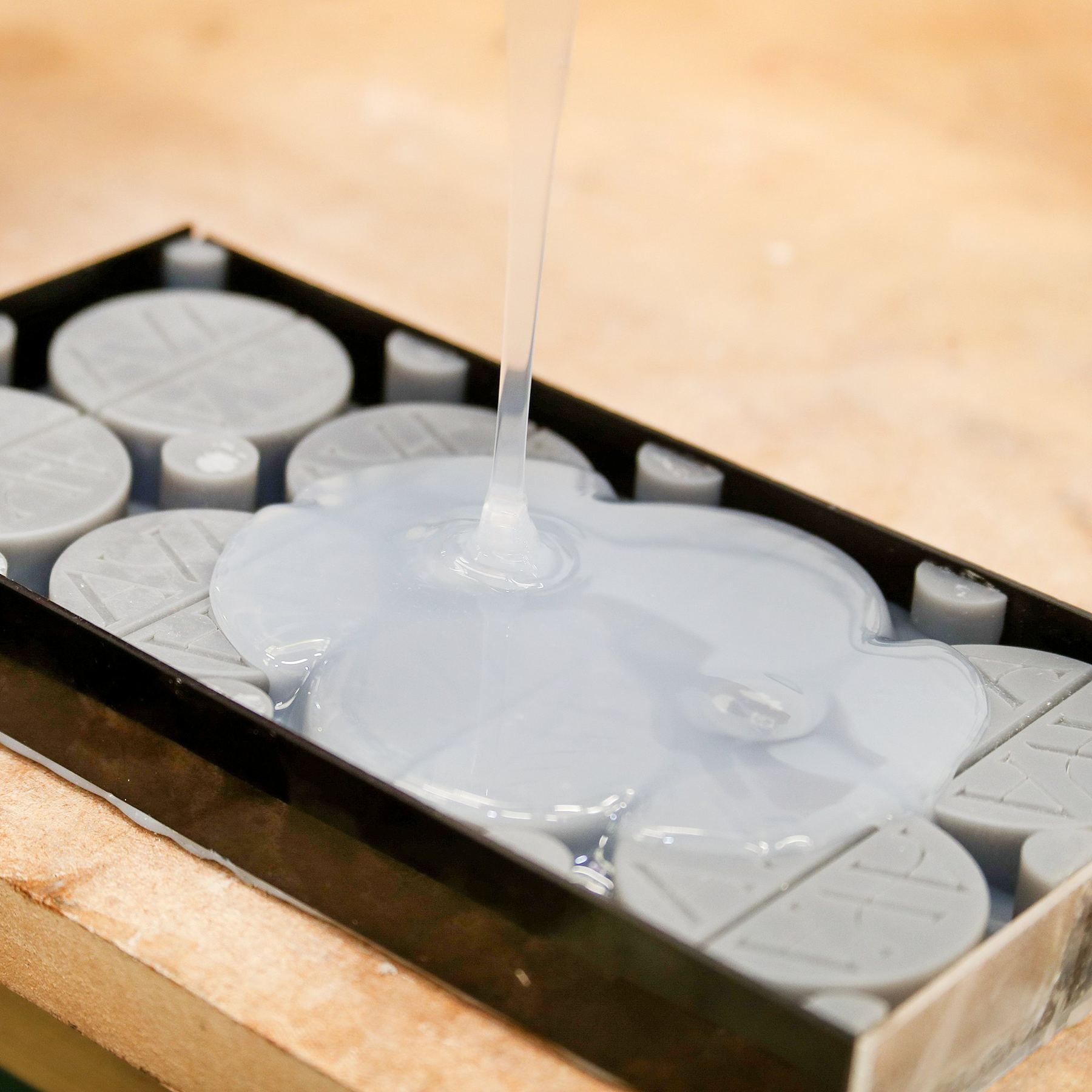
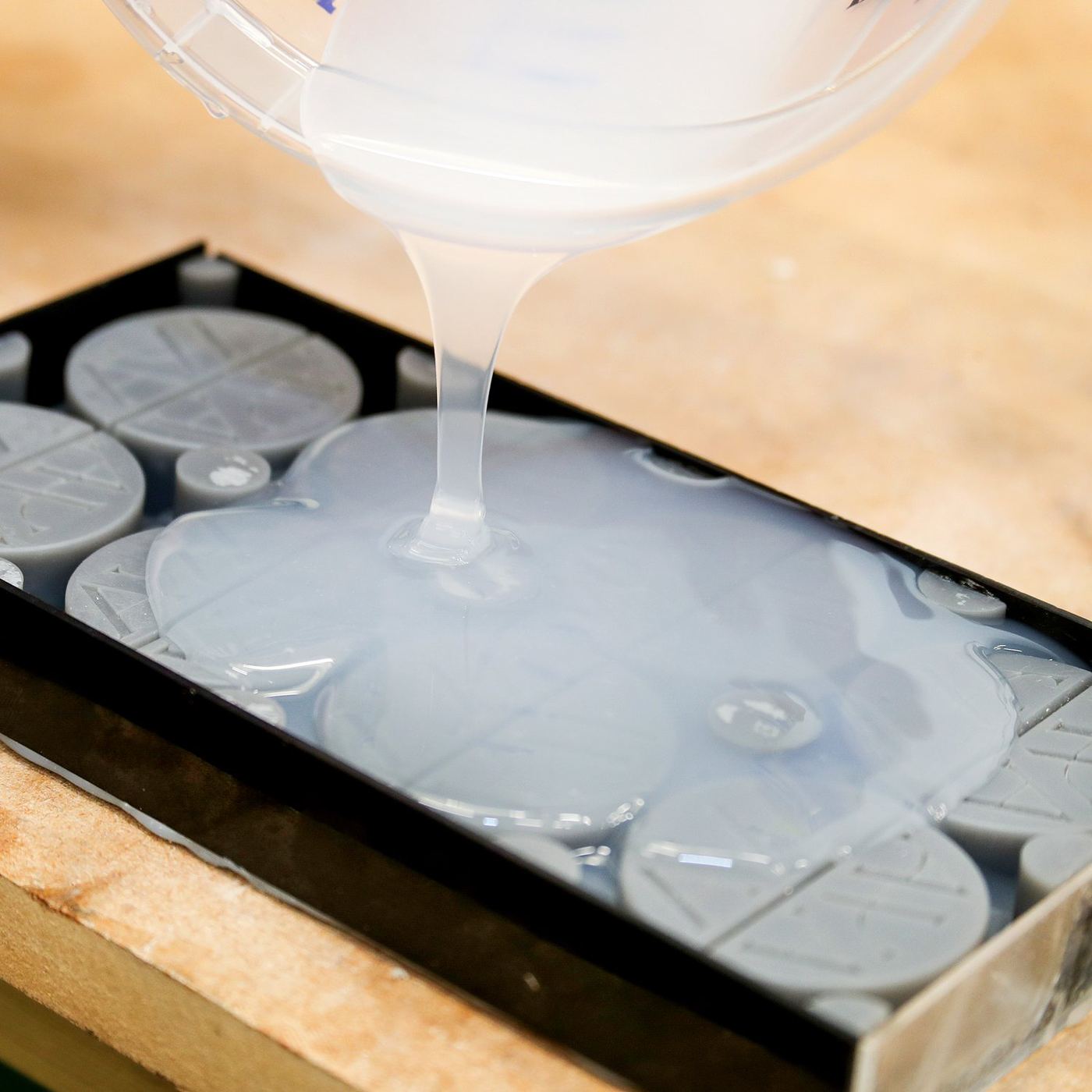
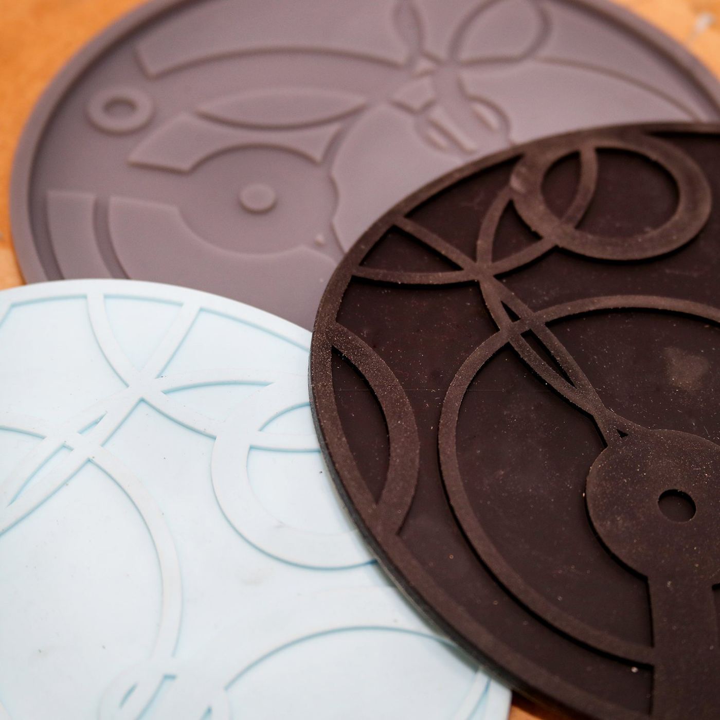
A master is fixed in a mould box and liquid silicone is poured over it. Ideal for one-off and short-run moulds with fine surface detail and deep undercuts.
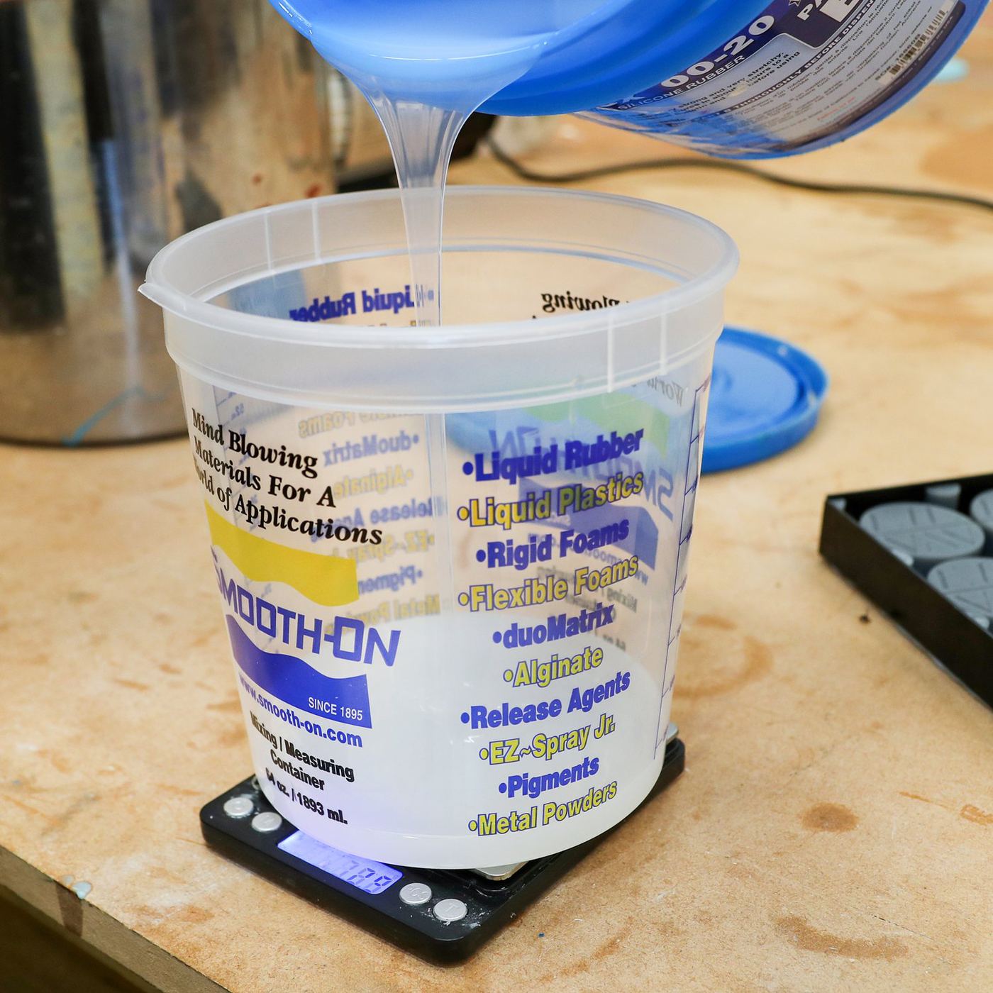
Two-part or multi-part silicone tools with registration keys and a planned parting line, made to cast resin, wax, soap, concrete or food repeatedly.
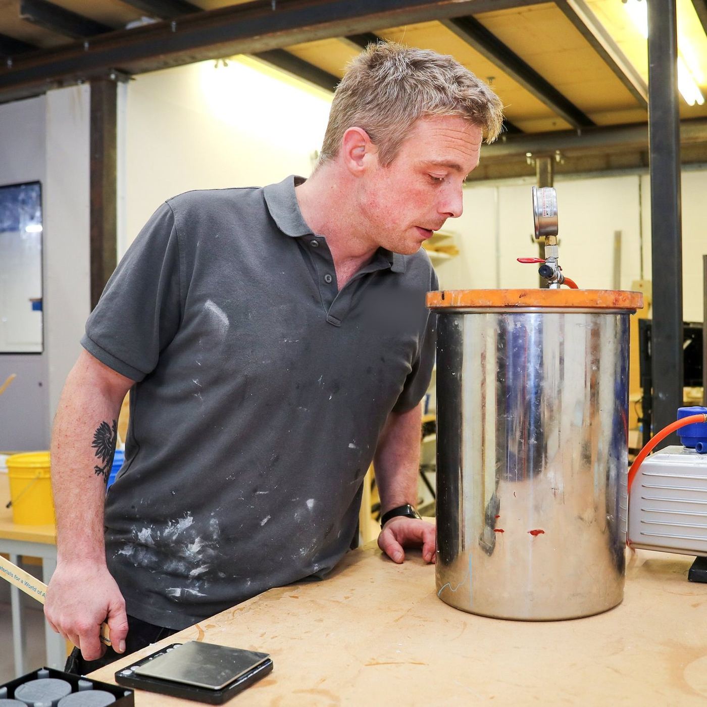
Resin is mixed and poured into a silicone tool under vacuum, removing air so thin walls and fine detail fill cleanly. The bridge from prototype to low-volume production.
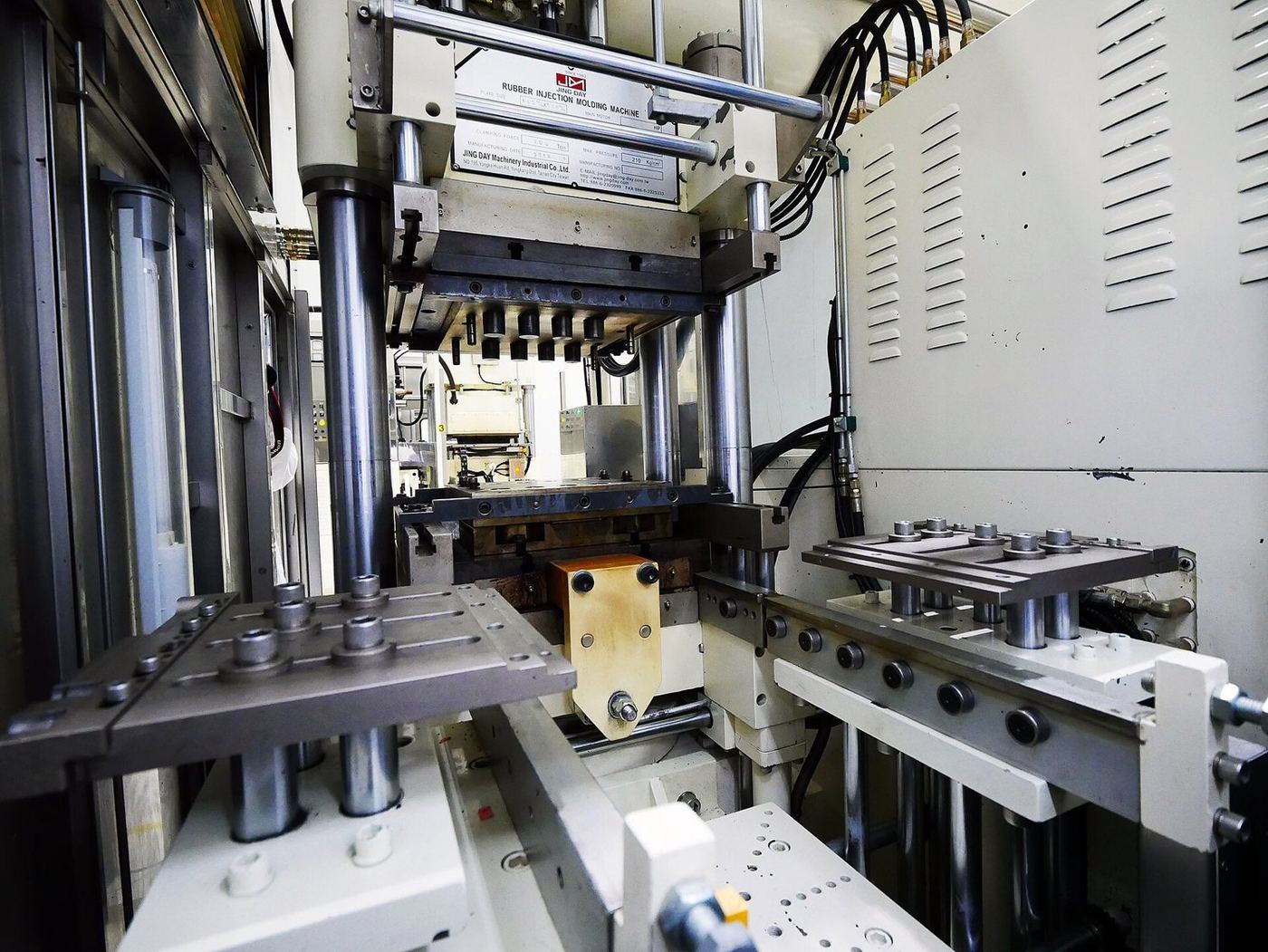
A measured charge of rubber or silicone is placed in a heated steel tool and pressed closed until it cures. Robust, economical tooling for seals, mats and solid rubber parts.
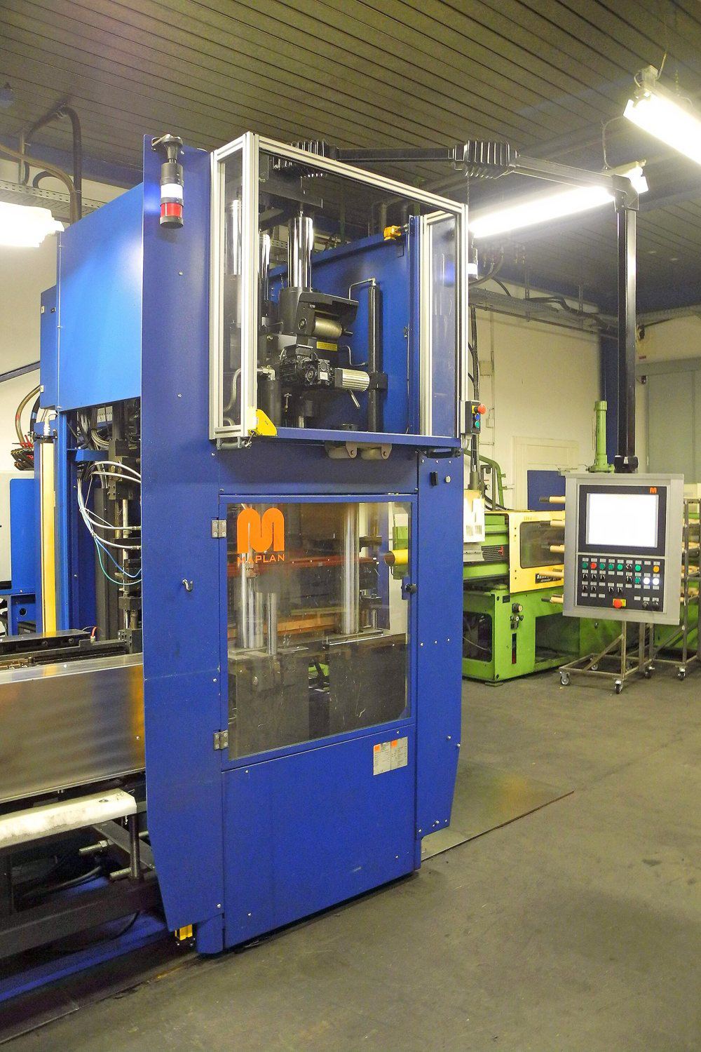
Rubber is loaded into a pot above a closed tool and forced through sprues into the cavities. Better control than compression for multi-cavity tools and parts with inserts.
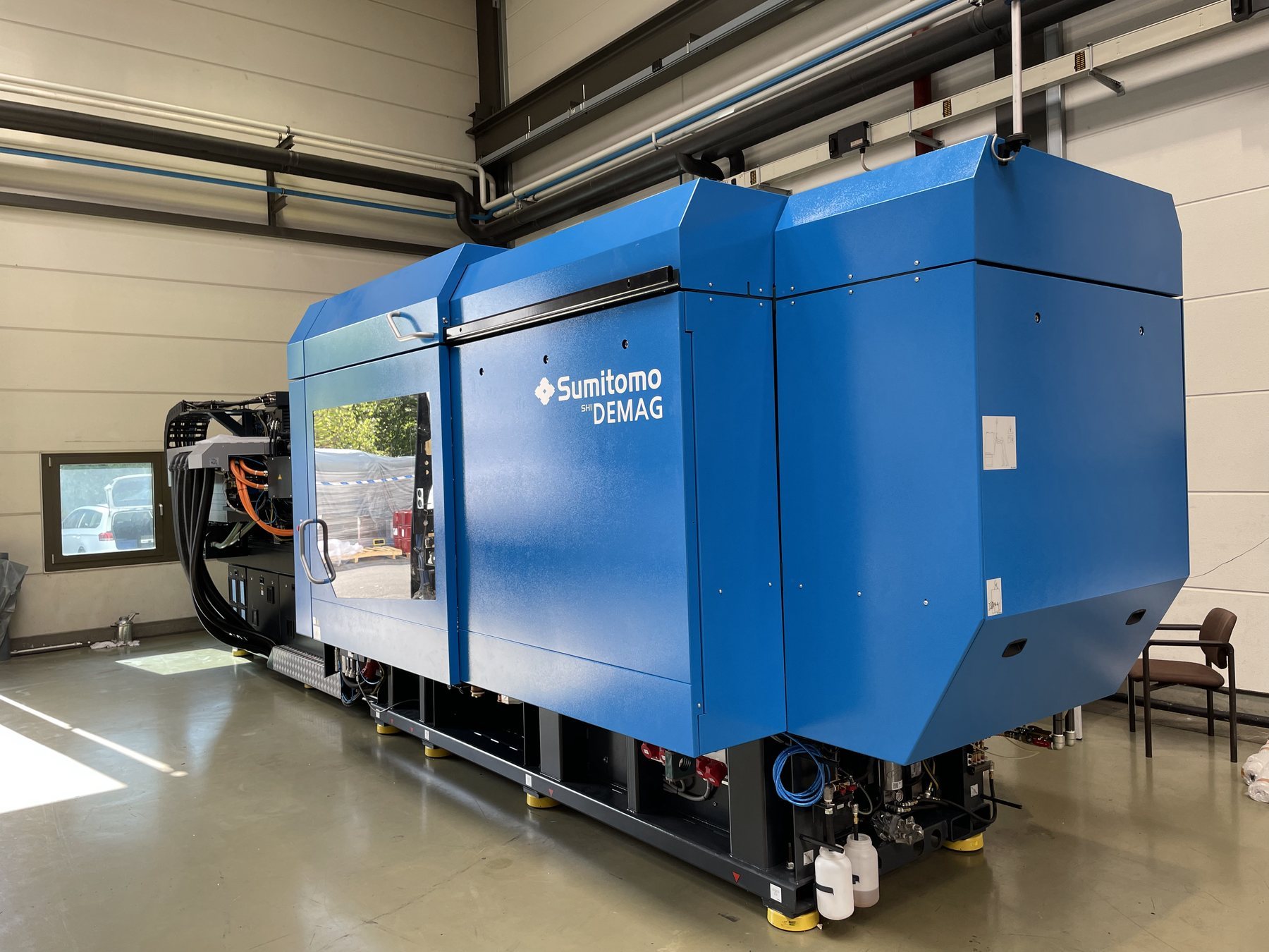
Two-part liquid silicone is metered, mixed and injected into a heated tool, curing in seconds. The route for high-volume, consistent silicone parts.
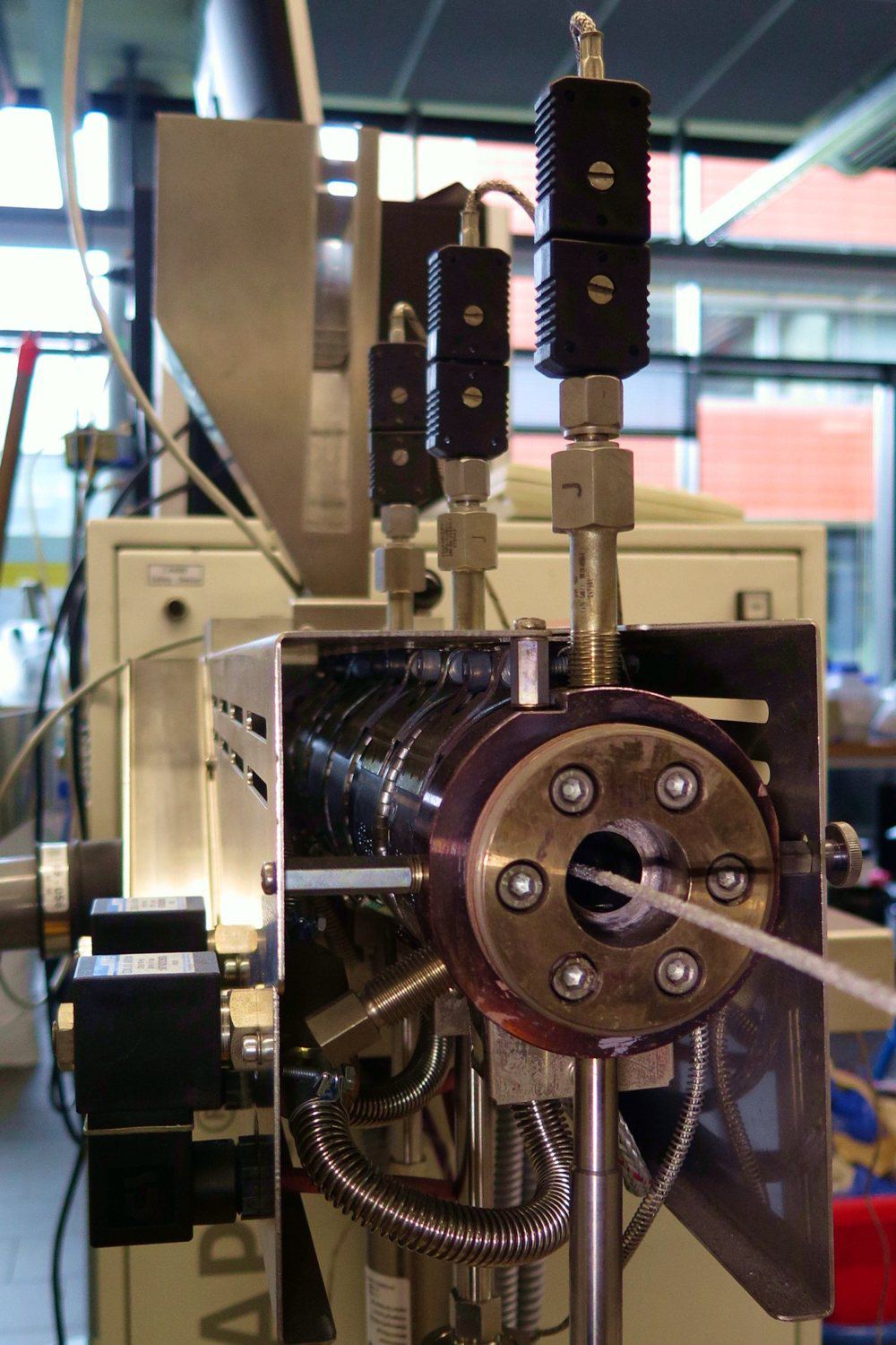
Uncured compound is forced through a shaped die to make continuous profiles, cords and tubes, then cured in a hot-air or salt-bath line.
Chapter B · 5 methods
Cast polyurethane for short runs, then injection-moulded and extruded plastics once volumes justify hard tooling.
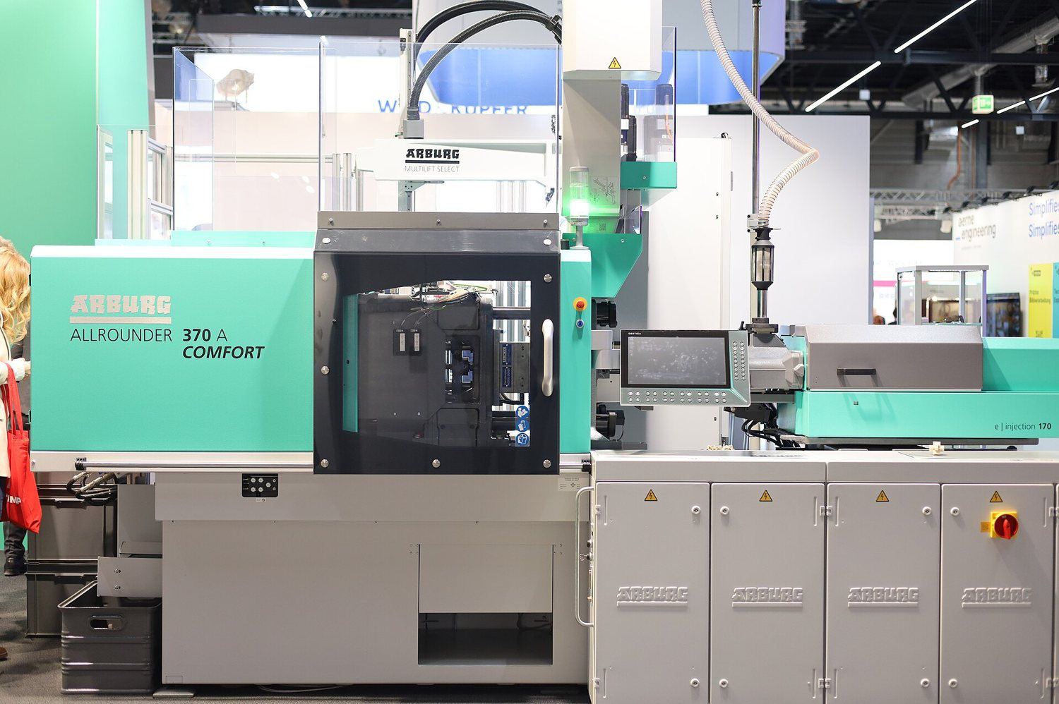
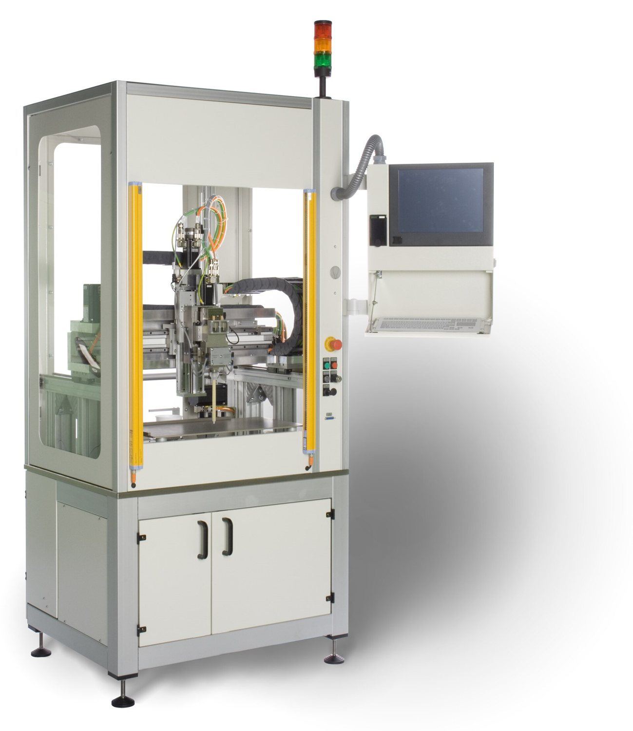
Two-part polyurethane is mixed and cast into silicone or rigid tools. Covers rigid, flexible and elastomeric parts without the cost of steel tooling.
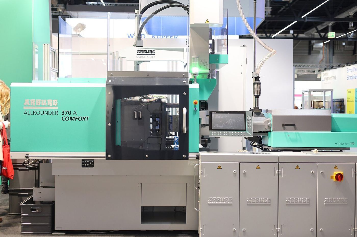
Molten thermoplastic is injected into a steel or aluminium tool, cooled and ejected. The lowest-cost route per part at scale.
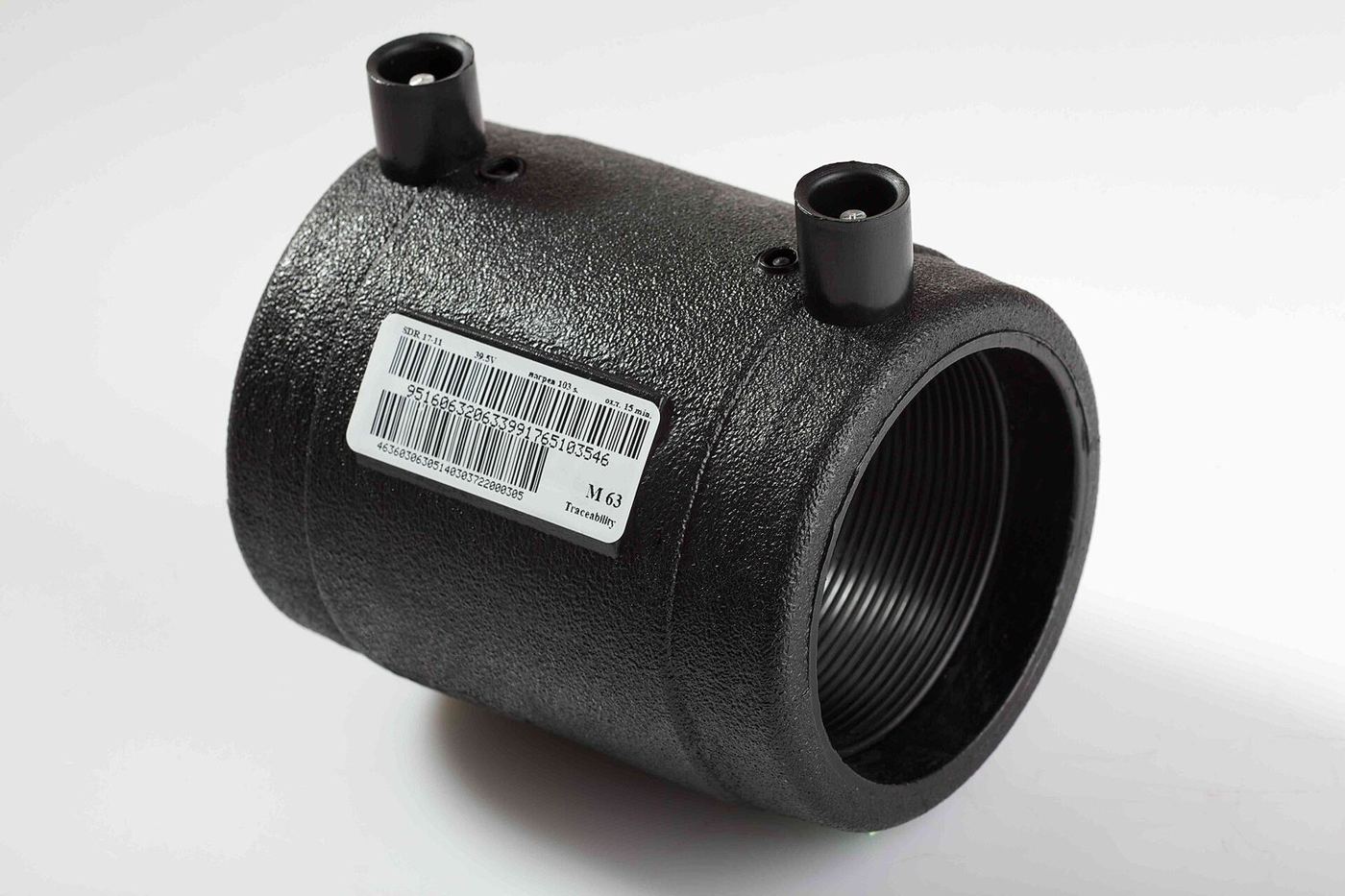
A metal or plastic insert is placed in the tool and plastic is moulded around it, giving a single bonded part with no secondary assembly.
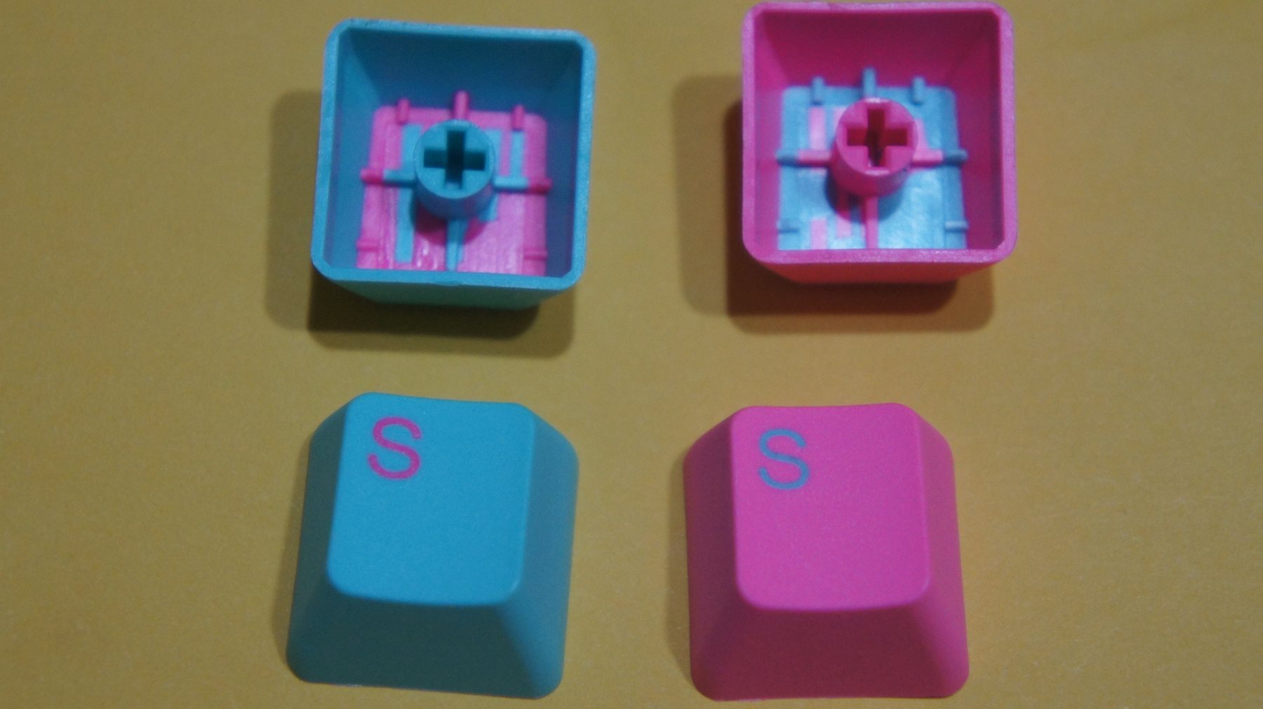
A second material, usually a soft TPE or silicone, is moulded over a rigid substrate to add grip, sealing or colour in one part.
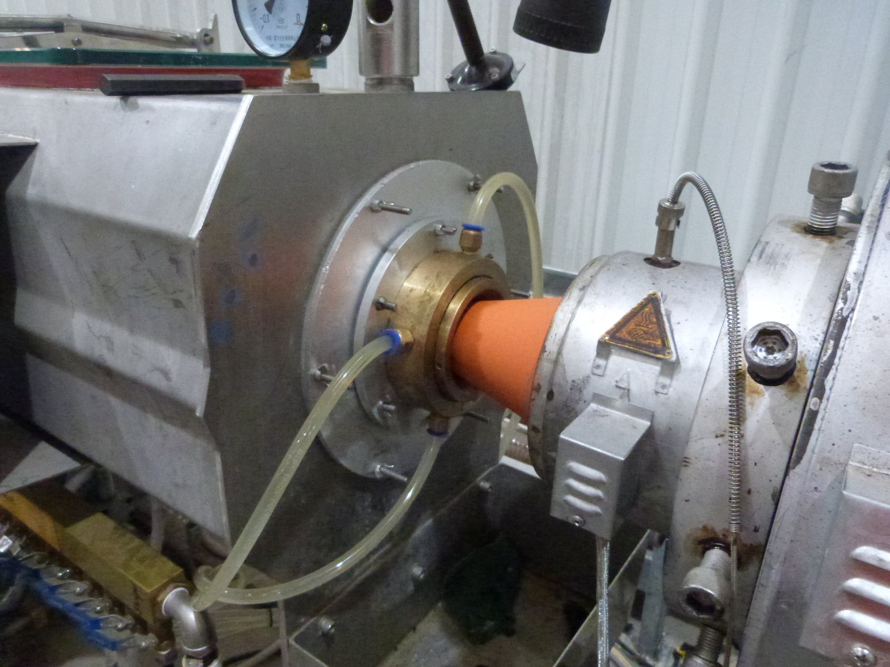
Thermoplastic is melted and pushed through a die to make continuous profiles, tubes and sheet, then cooled and cut.
Chapter C · 6 methods
Subtractive routes for master patterns, mould tools, fixtures and finished precision parts in metal and plastic.
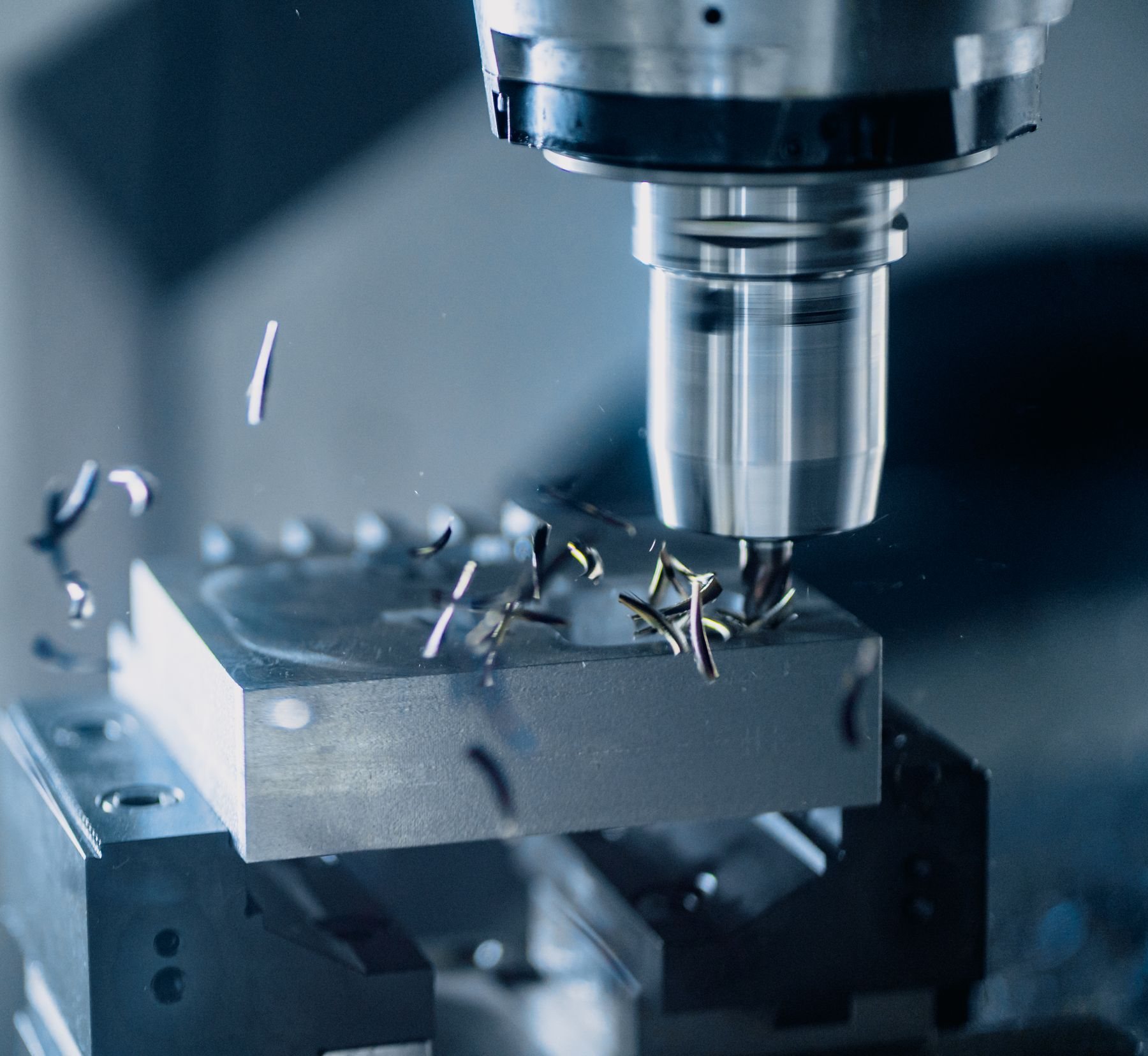
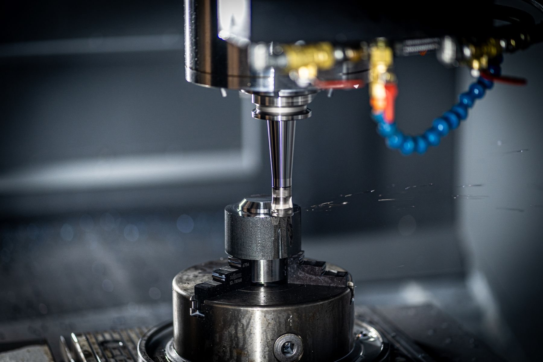
Rotating cutters remove material from a fixed block under computer control. Used for master patterns, mould tools and finished parts.
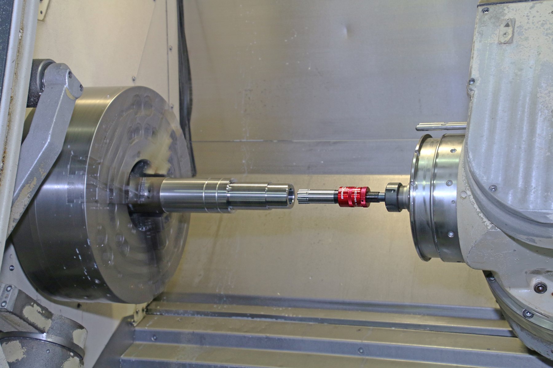
The workpiece rotates while a fixed tool cuts it, producing round parts such as shafts, pins and bushes quickly and accurately.
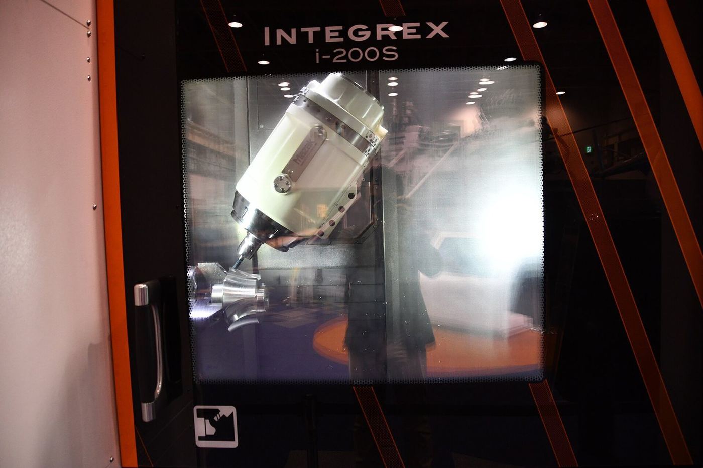
Extra rotary axes let the cutter reach more faces in one set-up. Essential for complex mould cores and sculpted master patterns.
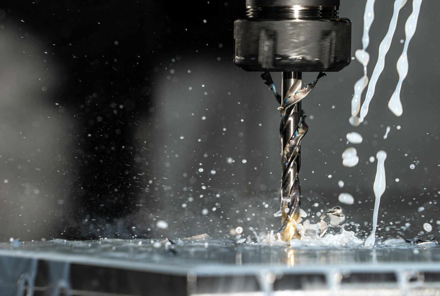
Holes are drilled, reamed or bored and then threaded with taps or thread mills, either on a CNC machine or as a dedicated operation.
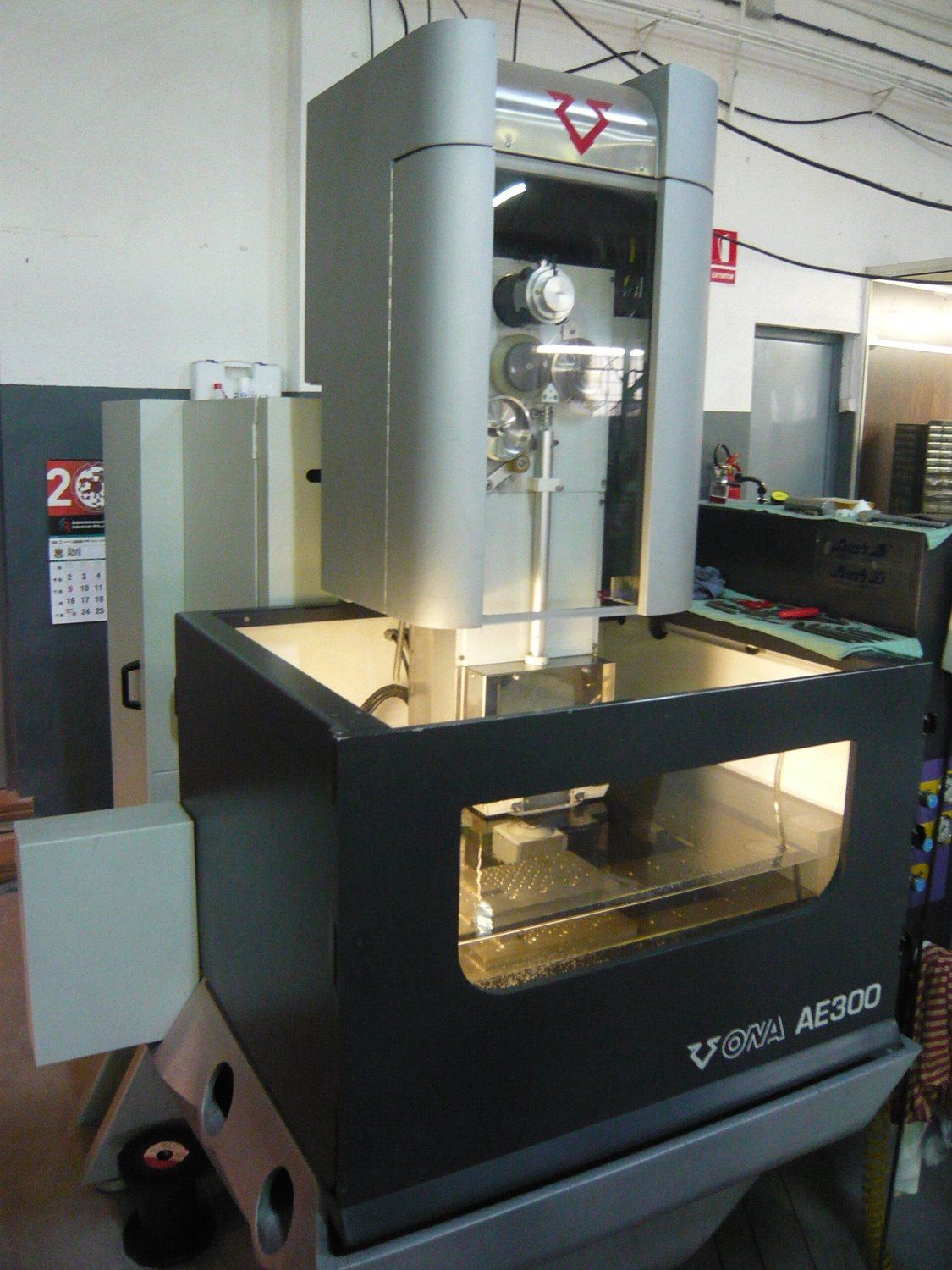
A thin charged wire cuts conductive metal by spark erosion, without cutting force. Produces sharp internal corners and very accurate profiles.
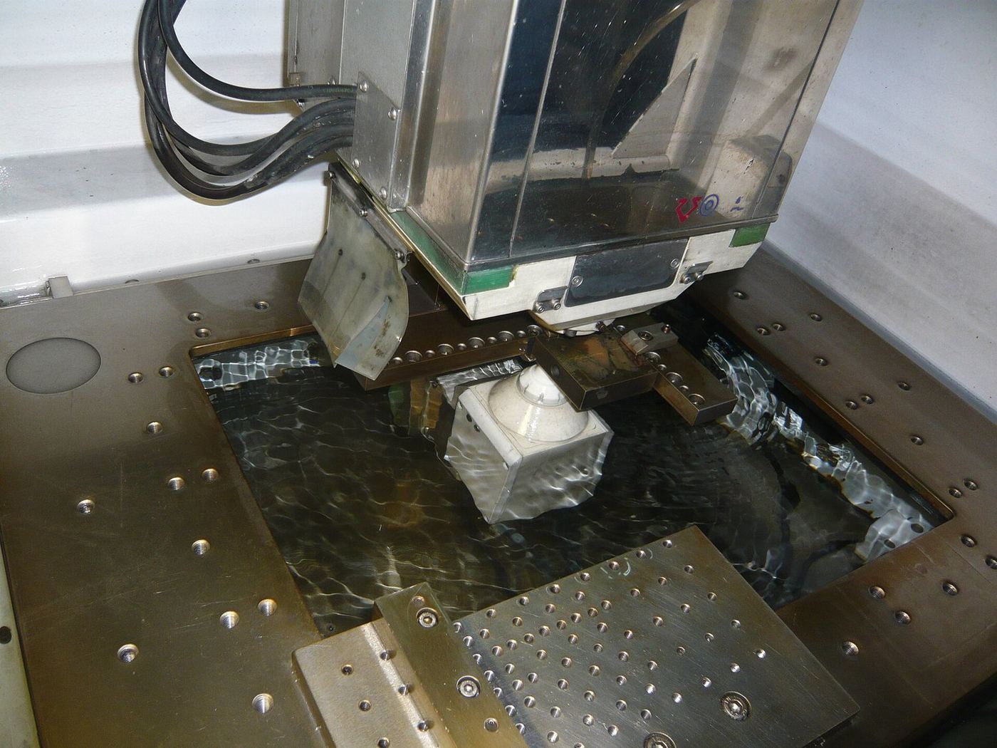
A shaped graphite or copper electrode is plunged into the workpiece under dielectric fluid, eroding its form into hardened steel.
Chapter D · 8 methods
Cutting, punching, bending and tube work for brackets, frames, enclosures and the stainless supports that carry many moulds.
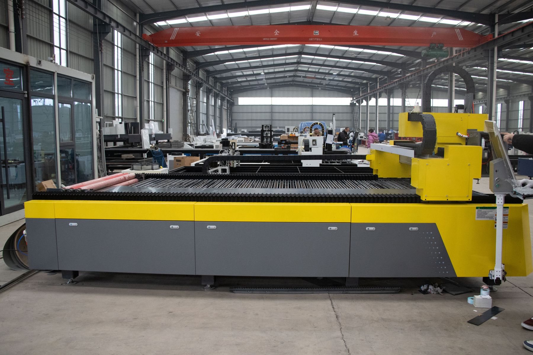
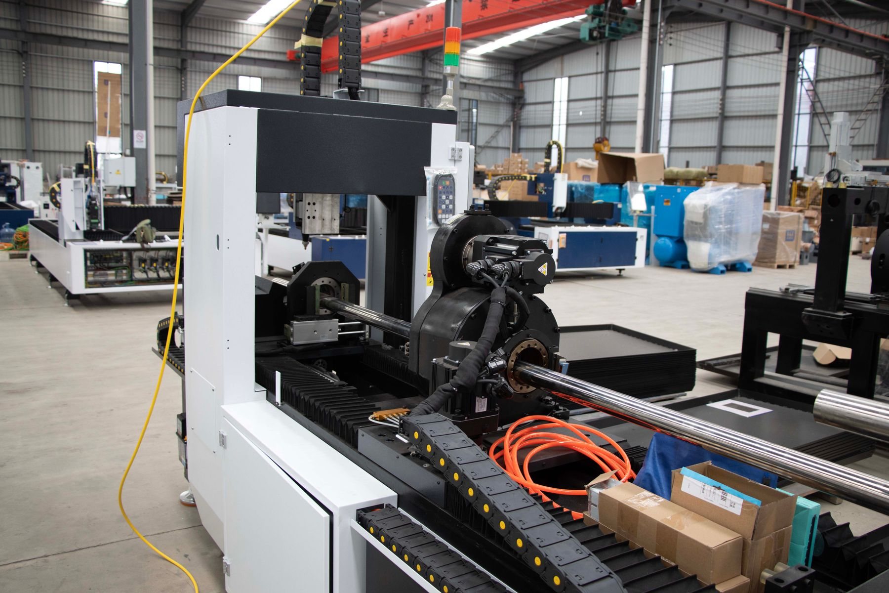
Flat sheet is cut, formed and joined into brackets, enclosures and frames. Fast and economical from one-offs to medium batches.
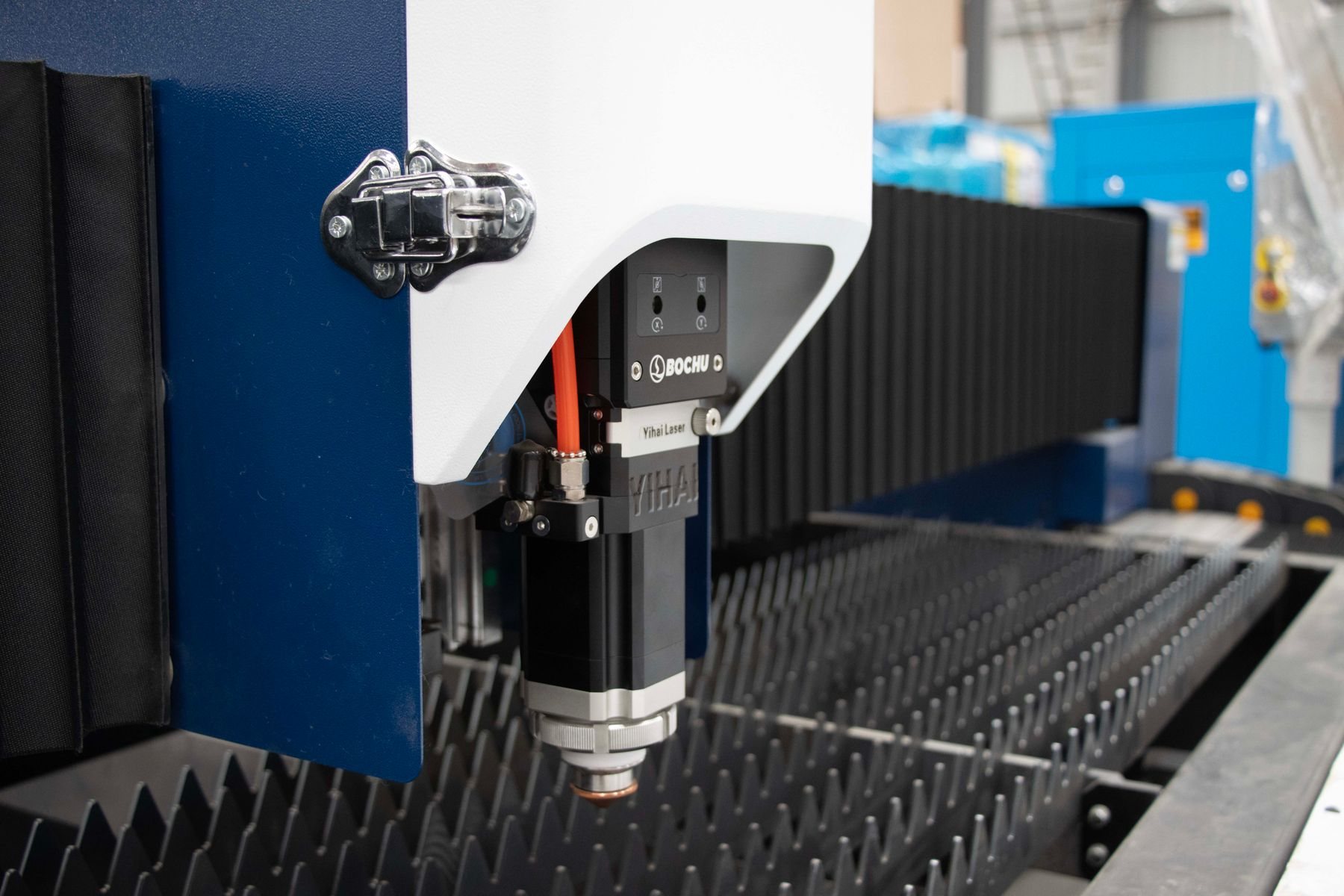
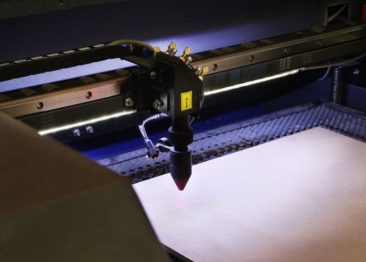
A focused fibre or CO2 laser beam melts or vaporises a narrow kerf, guided by CNC. Accurate, fast and burr-light on sheet and plate.
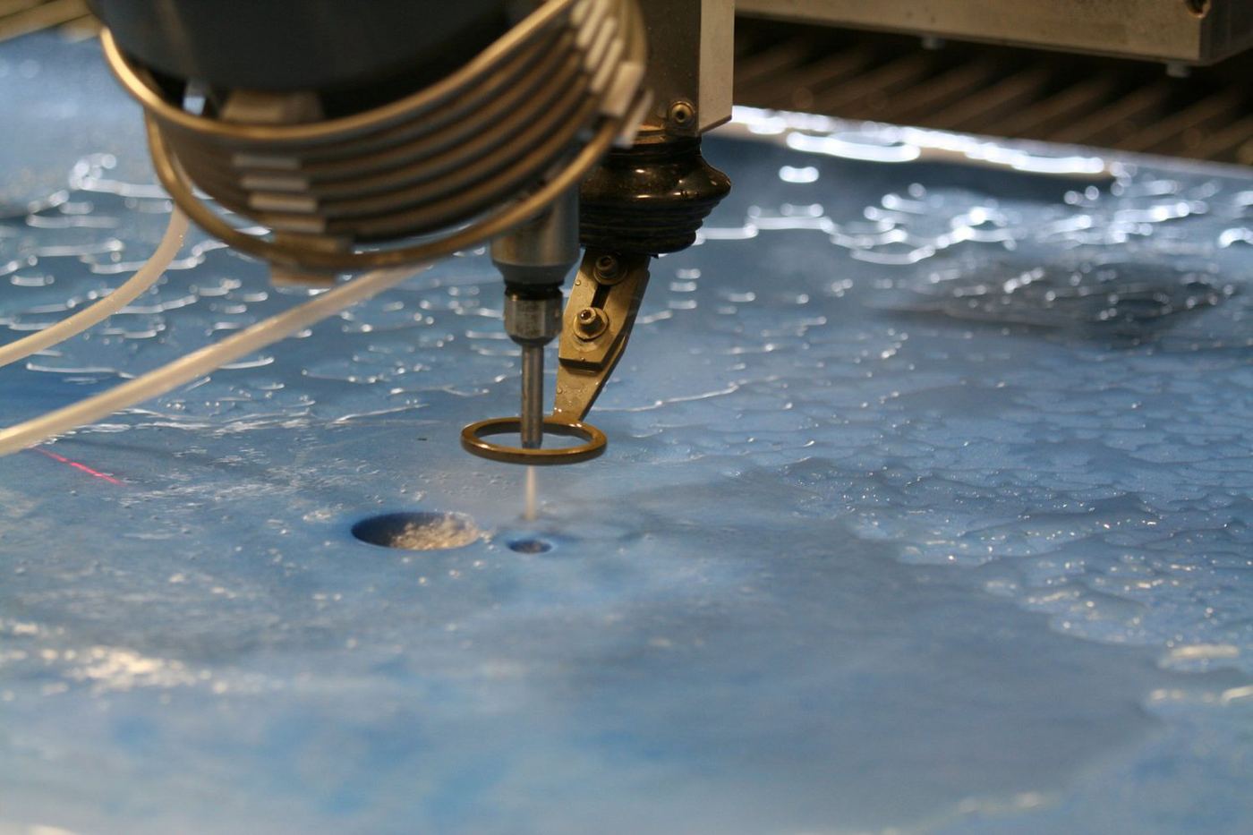
Ultra-high-pressure water, usually with garnet abrasive, erodes a narrow cut through almost any material with no heat-affected zone.
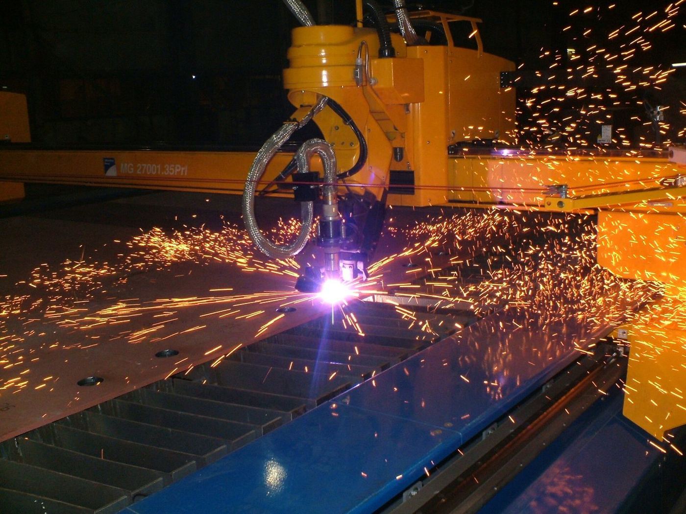
An electrically ionised gas arc melts and blows through conductive metal. Quick and economical for thicker steel plate.
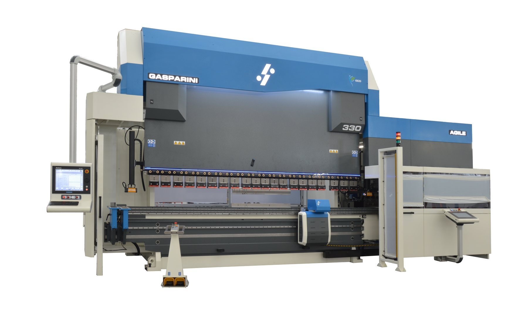
A press brake forces a punch into a V-die to bend sheet to an exact angle. Back gauges position each bend in sequence.
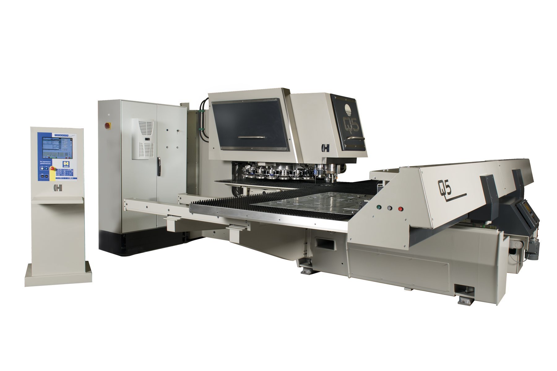
A CNC punch press strikes standard or special tools through sheet to create holes, louvres and formed features at high speed.
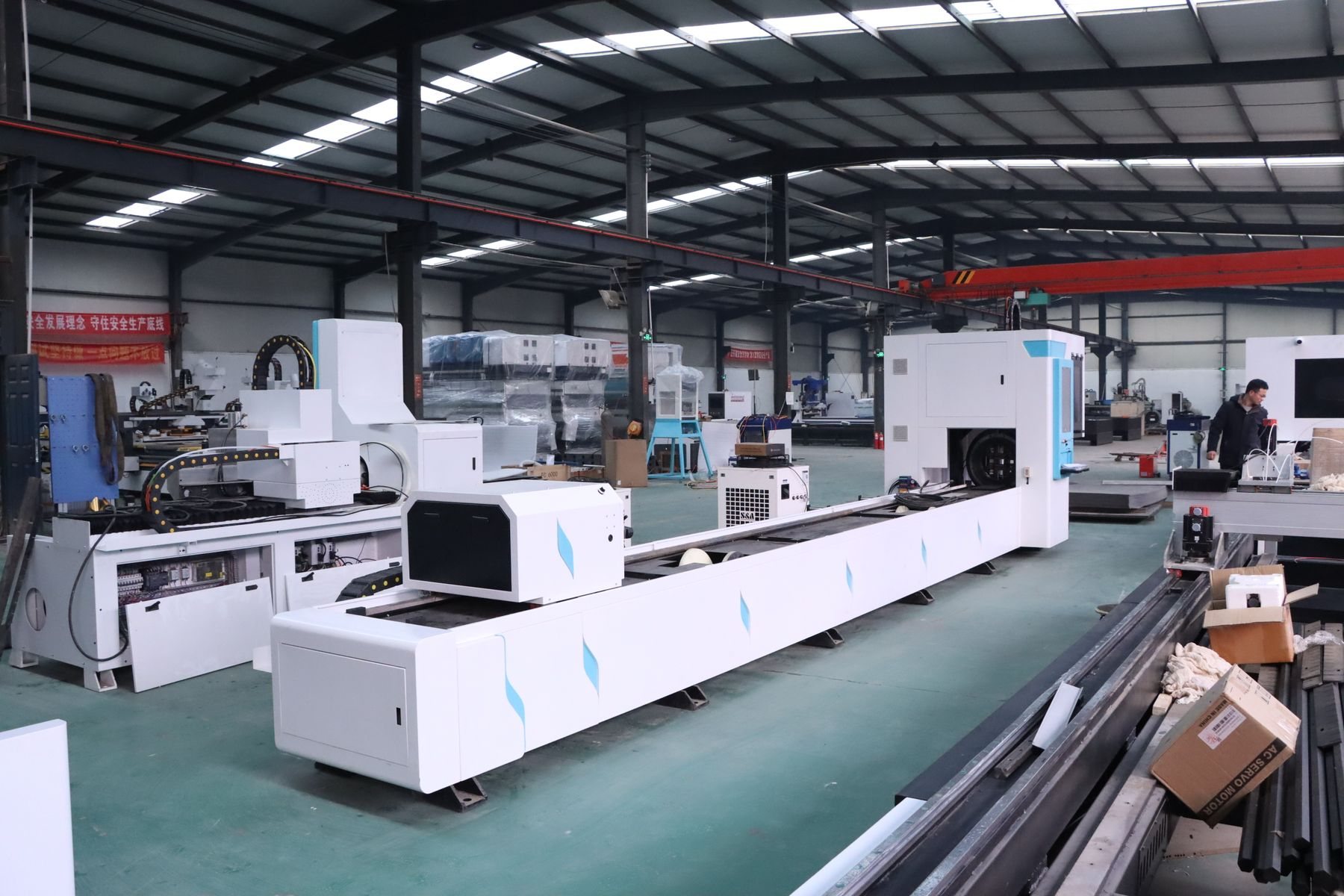
A laser head cuts holes, slots and end profiles in round, square and rectangular tube while a rotating chuck turns the tube.
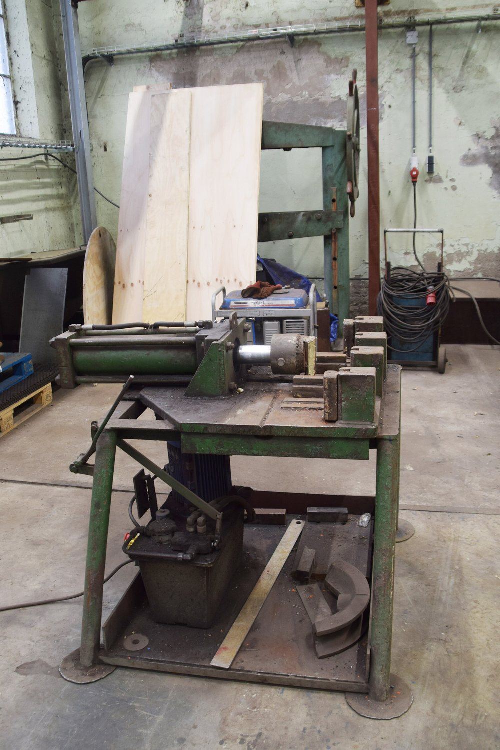
Tube is clamped to a bend die and drawn around it, often over a mandrel, to make smooth bends without kinking or wrinkling.
Chapter E · 5 methods
High-volume metal routes where the tool is the main investment and the part cost falls sharply with quantity.
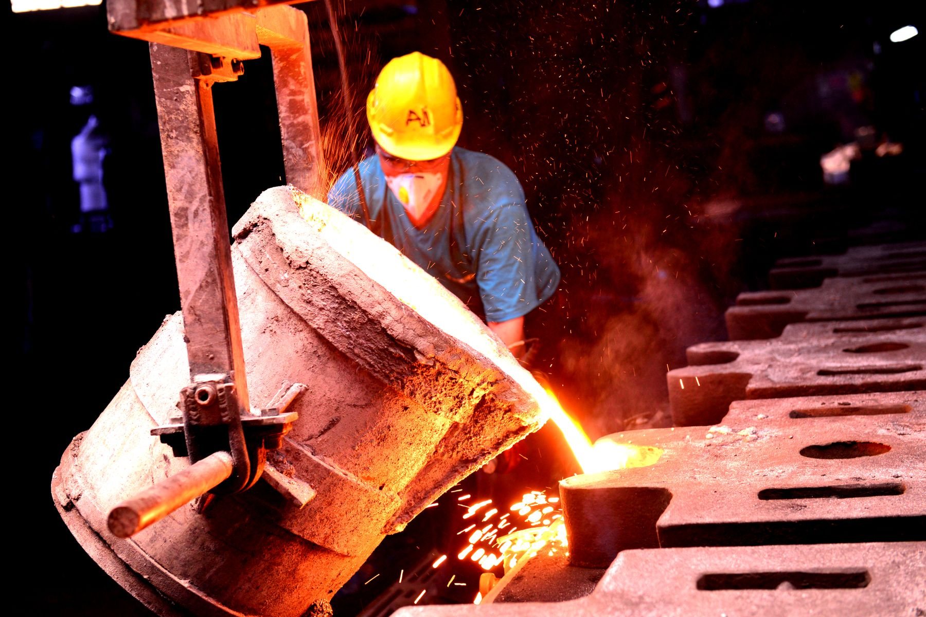
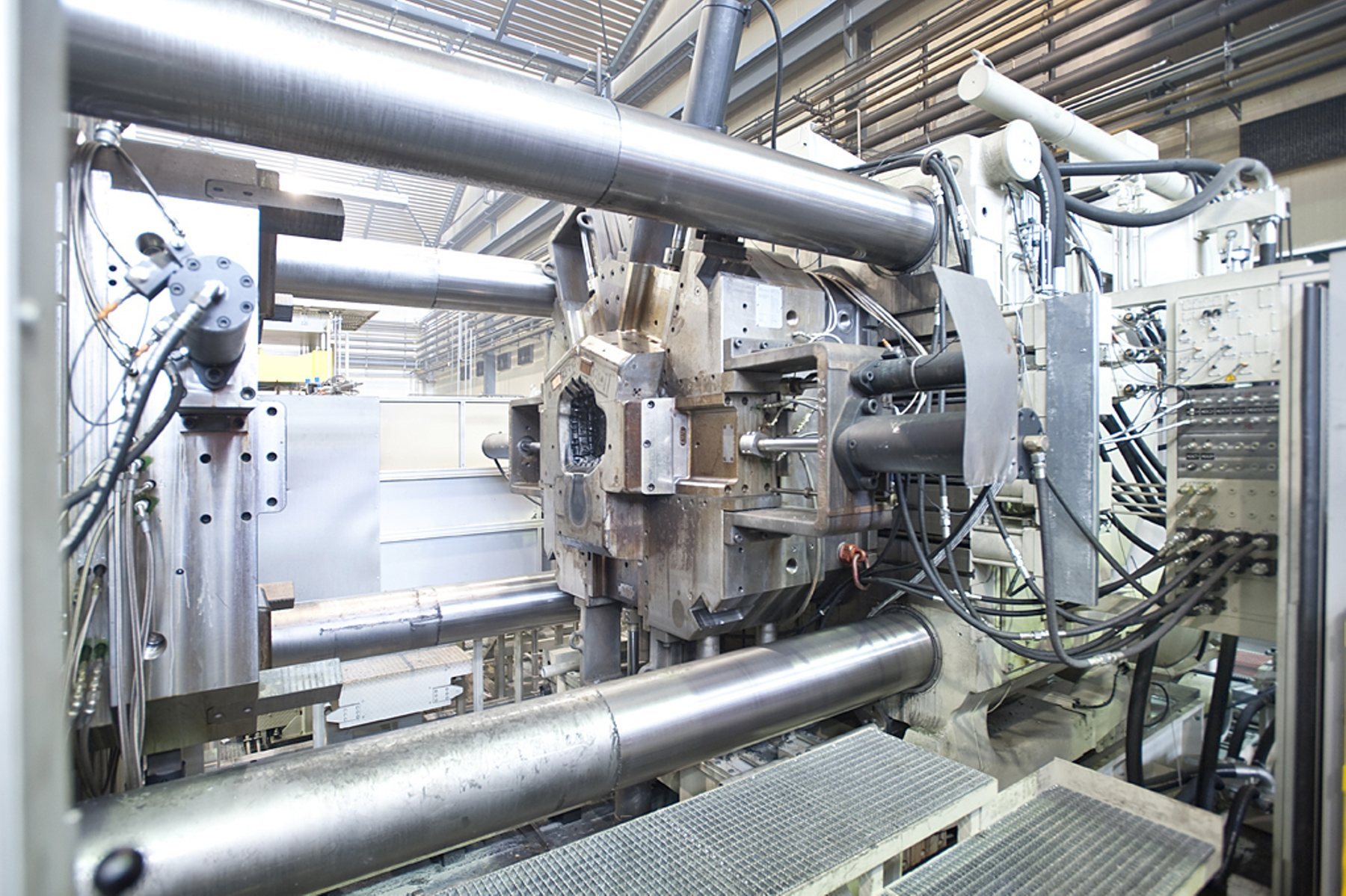
Molten aluminium or zinc is injected at high pressure into a steel die, producing accurate, thin-walled metal parts in high volumes.
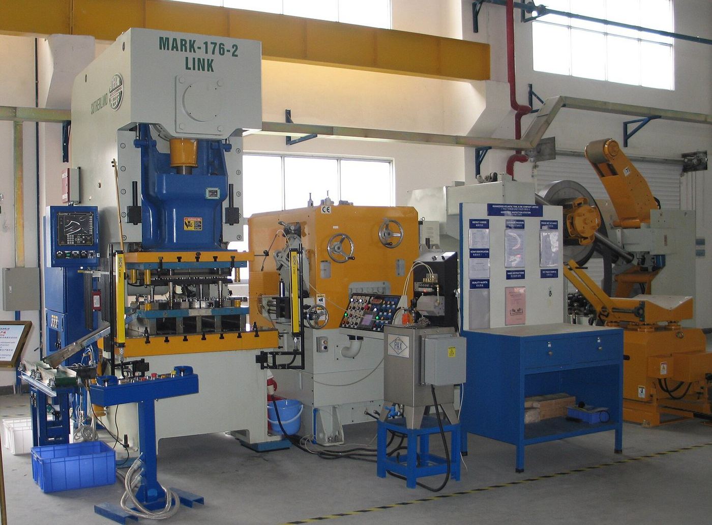
Coil or sheet is pressed between a punch and die to blank, pierce, bend or draw parts at very high speed.
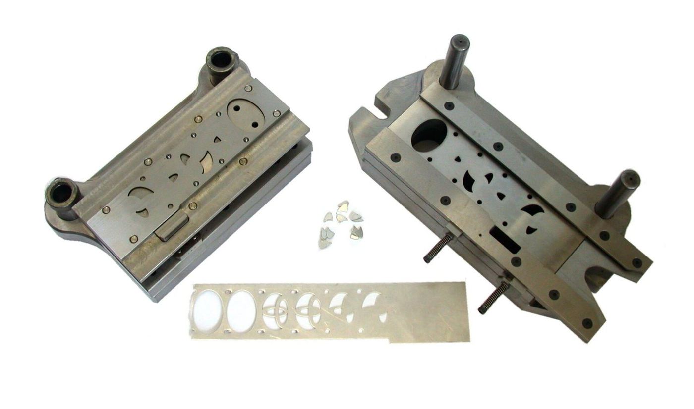
A strip advances through a series of stations in one die. Each stroke performs a step, and a finished part drops off the end.
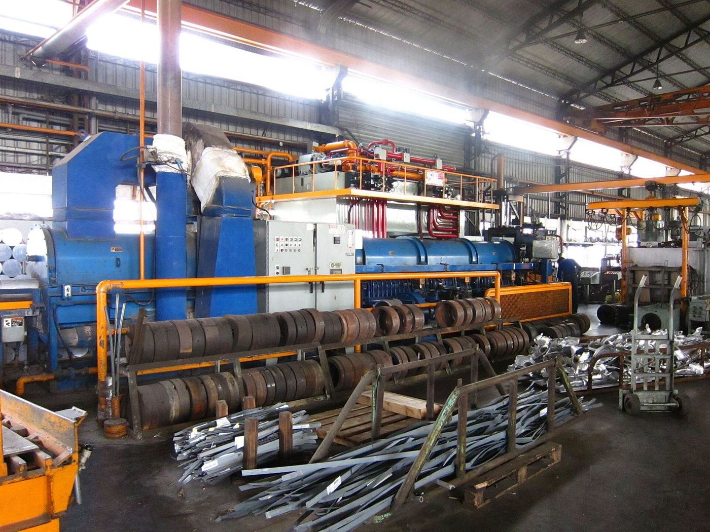
A heated aluminium billet is pushed through a shaped steel die to make long profiles with a constant cross-section.
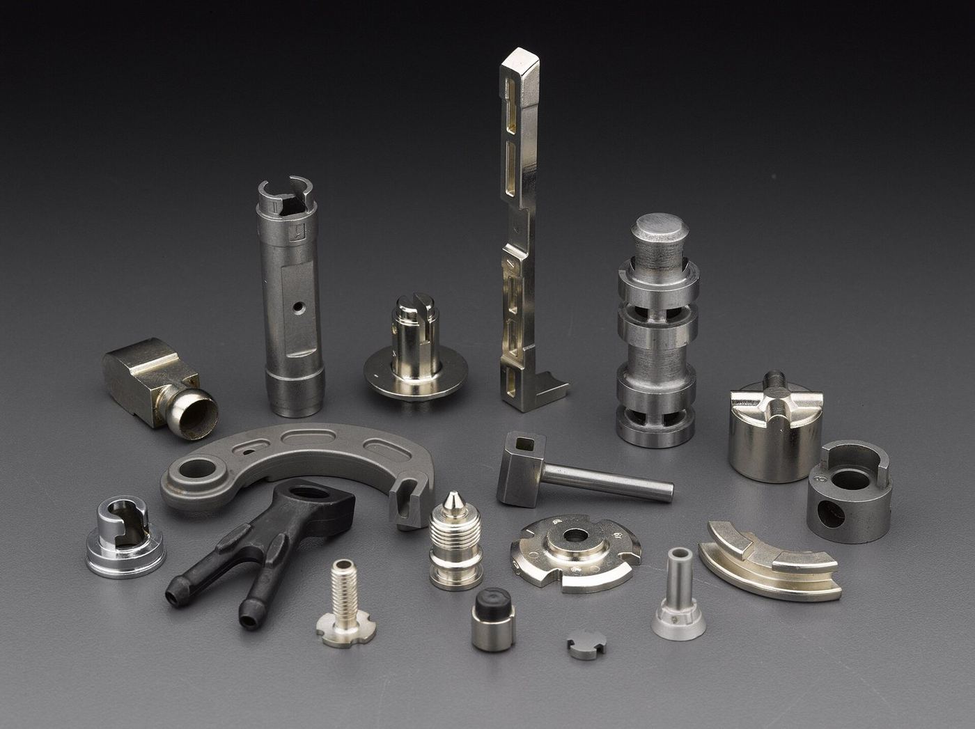
Fine metal powder mixed with binder is injection moulded, then debound and sintered into dense, small, complex metal parts.
Chapter F · 8 methods
Additive routes for master patterns, prototypes, jigs and short production runs, in polymer and metal.
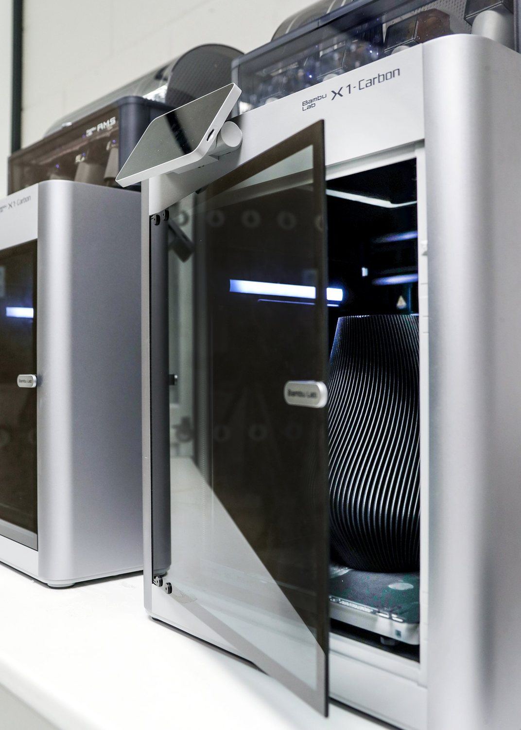
Thermoplastic filament is melted and laid down bead by bead, layer by layer. Quick and inexpensive for jigs, formers and concept models.
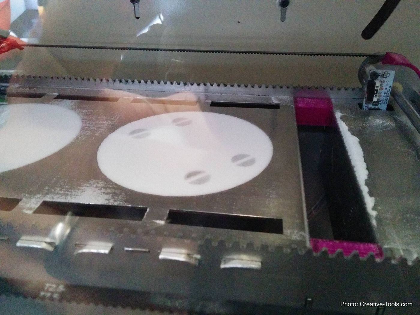
A laser fuses nylon powder layer by layer. Surrounding powder supports the part, so complex shapes need no support structures.
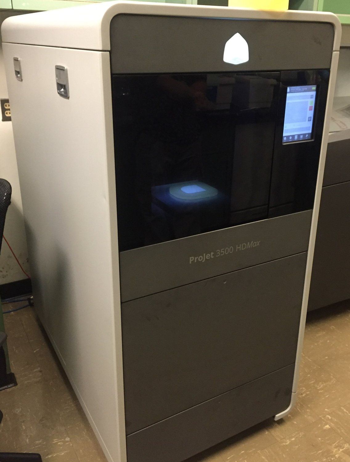
Inkjet heads print fusing and detailing agents onto nylon powder, then infrared energy fuses each layer. Fast and consistent for production quantities.
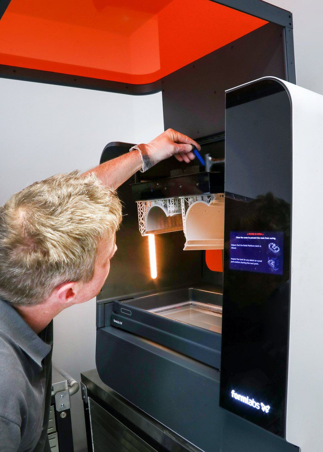
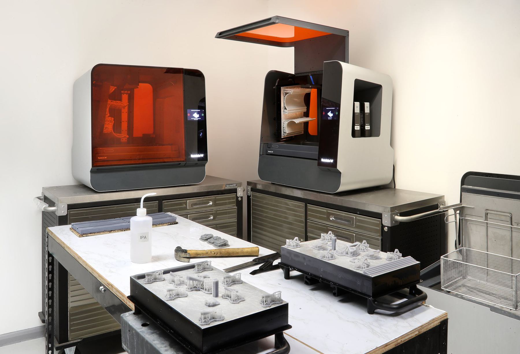
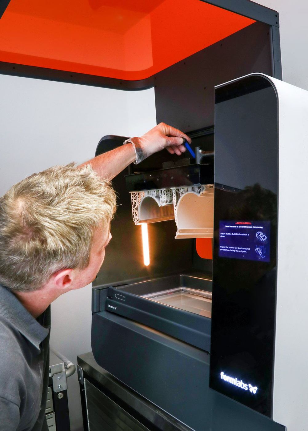
A UV laser or light source cures liquid resin layer by layer. Very smooth, detailed parts that make excellent master patterns for silicone moulds.
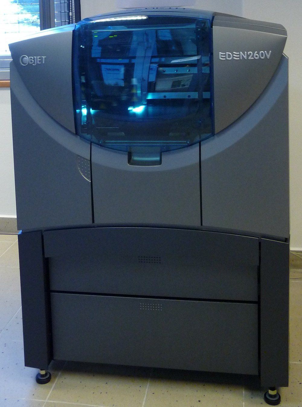
Printheads jet tiny droplets of photopolymer and cure them instantly with UV light. Mixes rigid, rubber-like and coloured materials in one print.
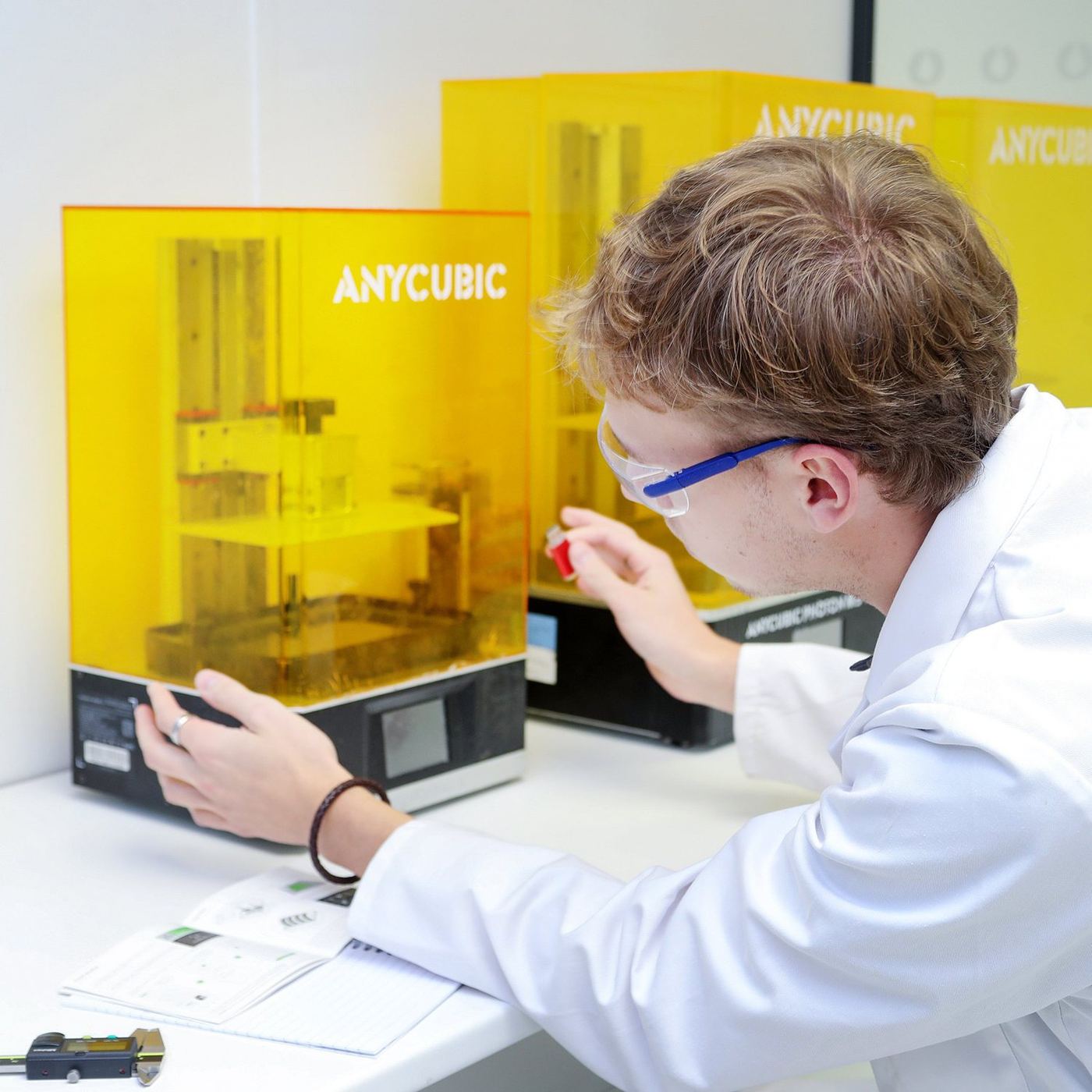
Digital Light Synthesis projects UV images through an oxygen-permeable window into resin, growing parts continuously. Then a thermal bake develops engineering properties.
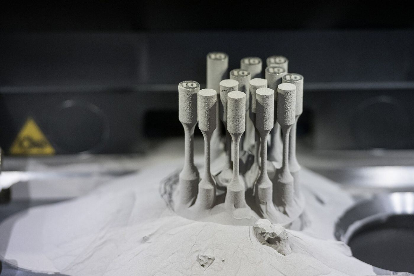
A laser melts fine metal powder layer by layer in an inert atmosphere, producing dense metal parts with internal channels and lattices.
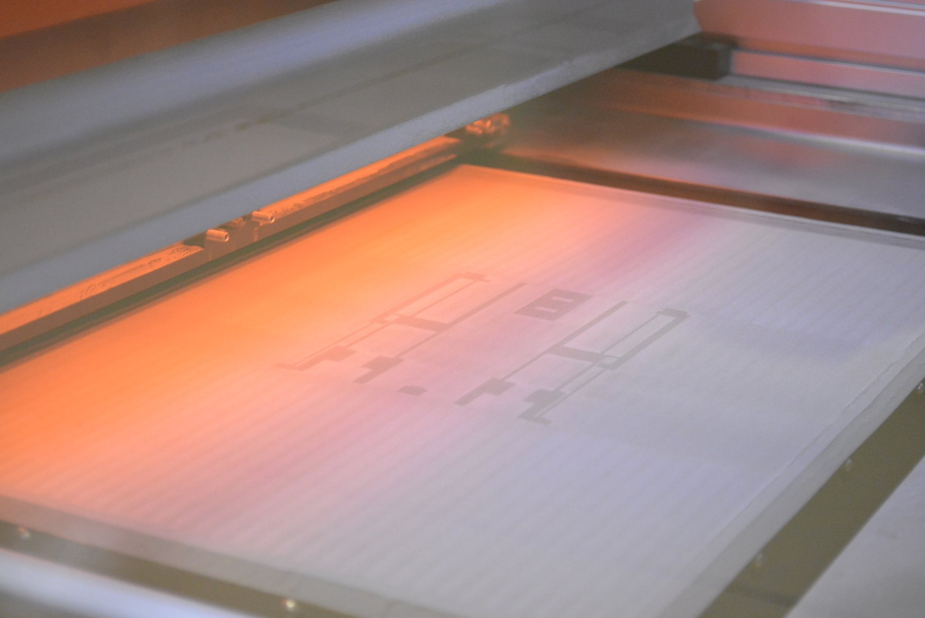
Printheads deposit binder into metal powder to form a green part, which is then sintered in a furnace. Faster and cheaper per part than laser melting.
Chapter G · 2 methods
Bringing components together into finished, checked and packed products.
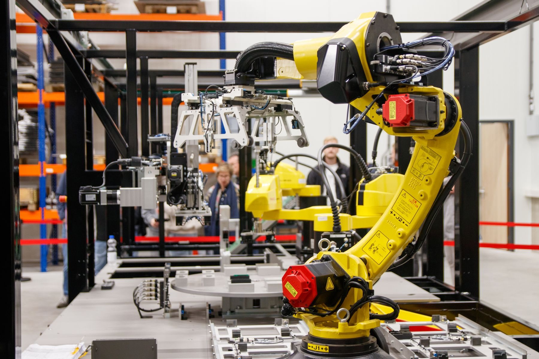
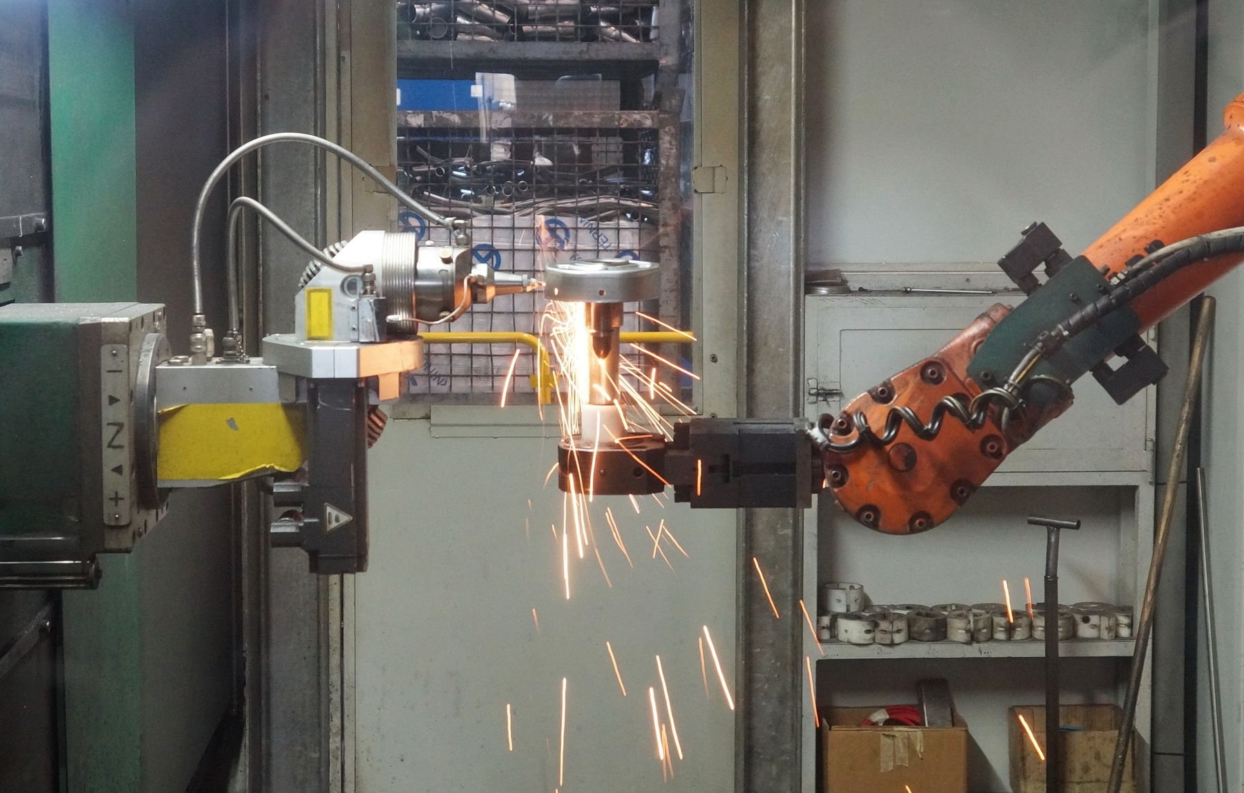
TIG, MIG and spot welding join metal components into frames and fabrications. Weldments combine cut, bent and machined parts into one assembly.
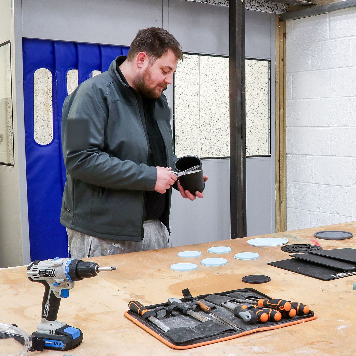
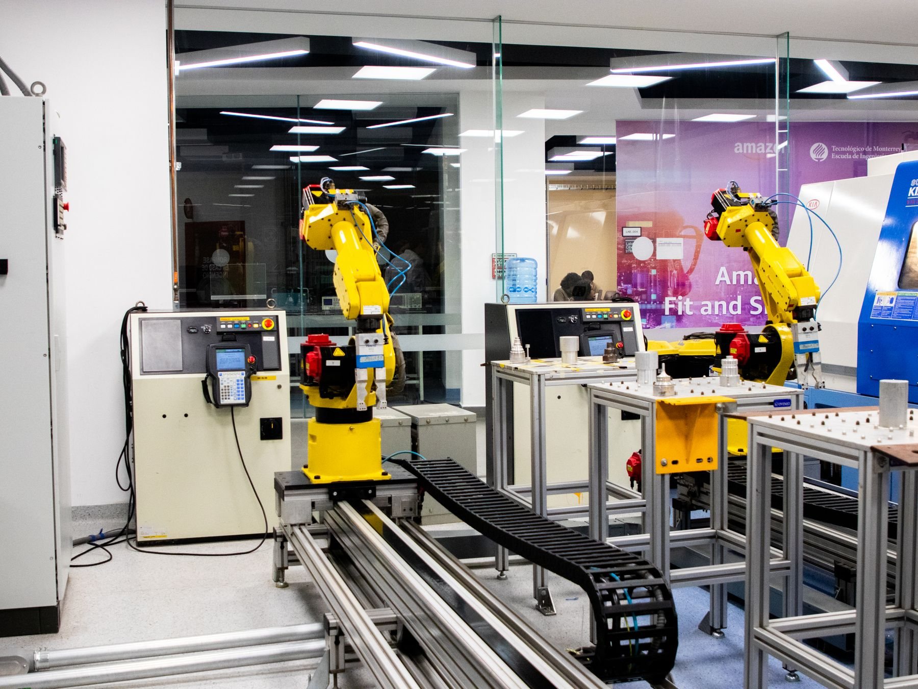
Bringing moulded, machined and bought-in parts together, with inspection, packing and labelling, so you receive a finished product.
Tolerance comparison
Typical general tolerances on a 25 mm feature, grouped by method family. These are planning figures; we confirm the tolerances we can hold on your drawing before any tooling or production starts.
Typical general tolerance on a feature around 25 mm (± mm); shorter bars are tighter. Larger parts, flexible materials and features across a parting line or bend usually need more allowance. Silicone and rubber parts are measured differently: we agree critical dimensions, Shore hardness and the measuring method with you at sample approval, usually against ISO 3302-1 tolerance classes for moulded rubber. Tighter tolerances are often possible on the features that matter; tell us which ones.
Material compatibility
Tell us the environment, such as temperature, chemicals, UV, food contact or flexibility, and we will recommend grades and confirm availability.
| Material family | Silicone and rubber | Plastics and PU | CNC machining | Sheet and tube | Metal production | 3D printing |
|---|---|---|---|---|---|---|
| Platinum-cure silicone (incl. food-contact grades) | Common | Selected grades | – | – | – | Selected grades |
| Tin-cure silicone | Common | – | – | – | – | – |
| EPDM, NBR, neoprene, FKM rubbers | Common | – | – | – | – | – |
| Polyurethane resins and rubbers | Common | Common | – | – | – | Selected grades |
| ABS, PC, acrylic | – | Common | Common | – | – | Common |
| PP, PE, TPE / TPU | – | Common | Selected grades | – | – | Common |
| Nylon (PA), POM, PEEK | – | Common | Common | – | – | Common |
| Photopolymer resins | – | – | – | – | – | Common |
| Aluminium alloys | – | – | Common | Common | Common | Common |
| Carbon and stainless steels | – | – | Common | Common | Common | Common |
| Brass, copper, zinc | – | – | Common | Common | Common | – |
| Titanium | – | – | Common | Selected grades | Selected grades | Common |
Food contact. For culinary moulds we specify platinum-cure silicones with supporting food-contact documentation. Base-material reports are checked against the finished mould’s actual use, colour and temperature.
Finishes overview
The finish is decided early: it is set by the master, the tool surface or the secondary process.
| Family | Typical finishes | Design note |
|---|---|---|
| Silicone and rubber | Matte, satin or gloss copied from the master; textured masters; pigmented colours; post-cured for stability | Finish is set by the master or tool surface |
| Plastics and PU | Polished (SPI A–C), matte (SPI D), VDI 3400 spark-erosion textures; painted, pad-printed or colour-matched | Texture adds draft: allow about 1° extra per 0.025 mm depth |
| CNC machining | As machined (about Ra 3.2 µm), bead blasted, anodised (Type II / III), powder coated, plated, polished | Specify cosmetic faces on the drawing |
| Sheet and tube | Deburred, brushed, powder coated, galvanised, zinc plated; laser-etched marking | Coatings add thickness to holes and fits |
| Metal production | As cast with light parting-line marks; shot blasted, machined faces, anodised, powder coated, chromate | Cast skins can show flow lines on show faces |
| 3D printing | As printed, sanded, vapour smoothed, dyed black, primed and painted, clear coated | Layer lines vary by build orientation |
Route to production
Every project follows the same clear route, so you always know what you are approving and what happens next. Highlighted stages are where we ask for your sign-off.
Sketch, photo, sample or CAD with quantity, material, finish and target date.
Faithful renders and a plain-English explanation of the route before any engineering.
Printed, machined or supplied master; early samples to check fit and feel.
Silicone, aluminium or steel tooling to suit volume and finish.
First-off parts measured and signed off against agreed dimensions.
Moulding, casting, printing or fabrication to the approved sample.
Checks, assembly, packing and delivery with records retained.
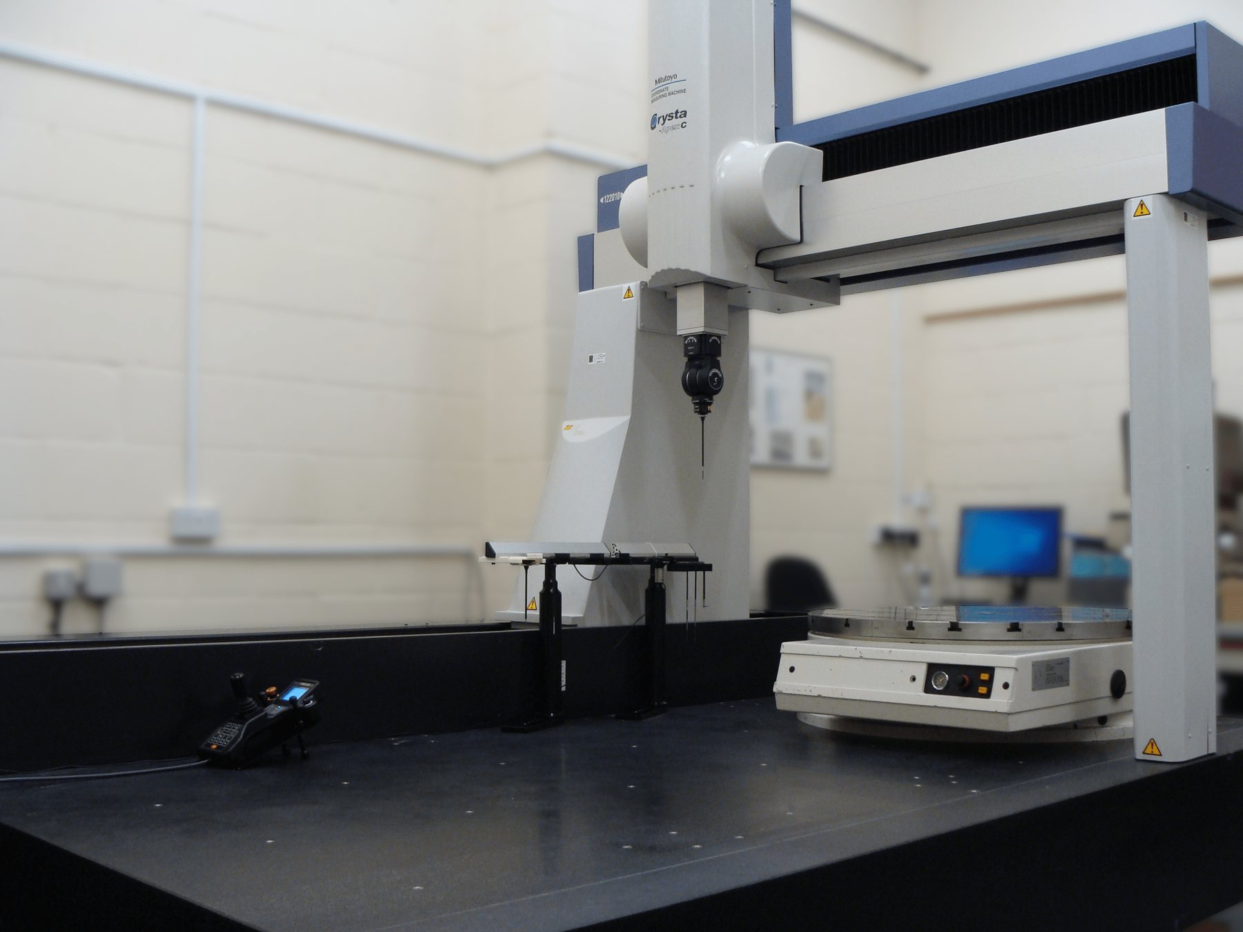
We show you faithful renders and talk the route through first. Quotations follow once the approach is agreed.
Approved baselines stay fixed. Alternatives are handled as separate, signed change requests.
Sample approvals, material documentation and inspection results are filed against your project number.
Sourcing
If a part or material is better made elsewhere, we find the right maker, check the samples and manage the supply, so you still deal with one team.
We match each part to the process, material and factory that suit your volume and budget.
We can compare UK and overseas manufacture and explain the trade-offs in cost, quality and lead time.
First-off samples are checked against your drawing before production is released.
We can source silicones, rubbers, plastics, metals, fixings, magnets and bought-in parts alongside your moulded items.
One TCI contact manages quotes, samples, quality and delivery across every supplier.
Material certificates, food-contact declarations and inspection records collected and kept with your job.
Next step
Tell us what the part needs to do and roughly how many you need. We will suggest the best route and tell you plainly if another process would suit you better.
How our one-stop service works
About the figures: tolerances, finishes and limits on these pages are typical published industry reference values for planning. Final tolerances, materials and finishes are agreed in writing for each project. Photos marked “TCI workshop” were taken in our own workshop. Other photos are free-licence images from Pexels, rawpixel and Wikimedia Commons, credited on each photo; they show the general process or equipment type rather than TCI’s own machines.