Spread
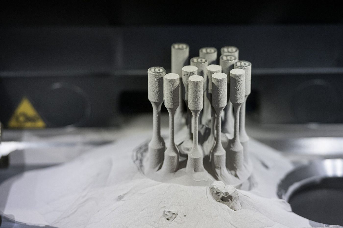
A recoater spreads metal powder.
Manufacturing services · Chapter F · Method 38
A laser melts fine metal powder layer by layer in an inert atmosphere, producing dense metal parts with internal channels and lattices.
How it works
A labelled schematic of the process (not to scale), and the four steps every job goes through.
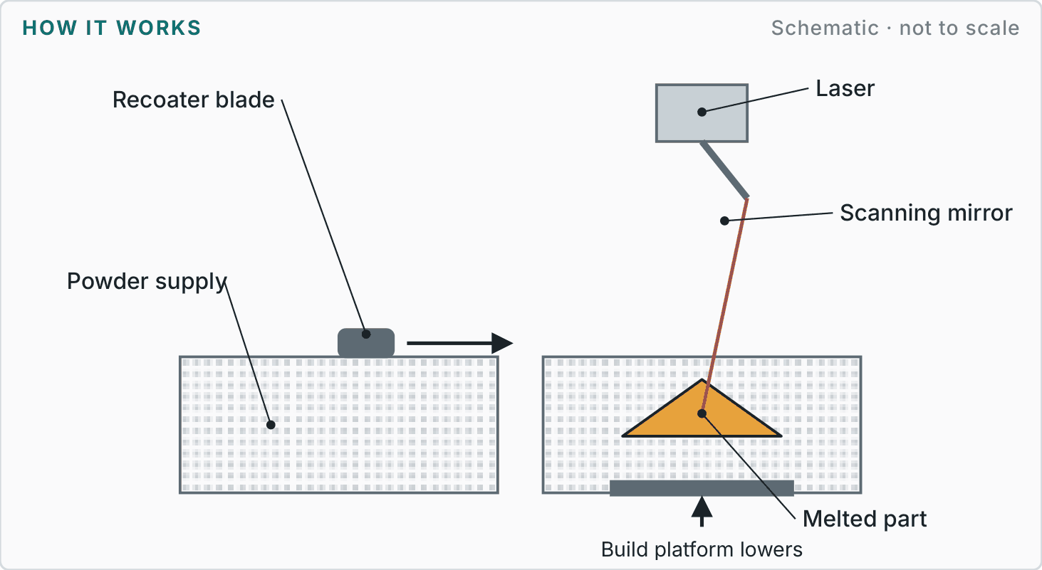
A recoater spreads metal powder.
The laser melts each cross-section.
Heat treat on the build plate.
Cut from plate, remove supports, machine.
Reference figures
Typical industry values to help you plan. We agree the figures for your part on the drawing.
| Materials | Stainless 316L and 17-4PH, aluminium AlSi10Mg, titanium Ti6Al4V, Inconel 625/718, maraging steel. |
|---|---|
| Finishes | Rough as built; bead blasted, machined, polished or heat treated. |
| Design guidance |
|
| Best suited to | Conformal-cooled mould inserts, aerospace brackets, manifolds and medical parts. |
| Watch-outs | High cost per part; flatness and threads usually need machining. |
More in chapter F
Next step
Send a sketch, photo, sample or CAD file with your quantity and target date. We will recommend the most sensible route and explain the trade-offs before quoting.
Reference figures are typical published industry values for planning, not a guarantee; final tolerances, materials and finishes are agreed in writing for each project.